
device for oral examination

An inspection device and oral technology, which is applied in the fields of oral mirror, medical science, endoscopy, etc., can solve the problems of increasing the workload of medical staff, difficult to observe clearly, limited oral space, etc., and achieves convenient observation, convenient use, and operation. handy effect

Active Publication Date: 2017-07-04
代雪松
View PDF9 Cites 0 Cited by
  • Summary
  • Abstract
  • Description
  • Claims
  • Application Information

AI Technical Summary

Problems solved by technology

[0003] However, due to the limited space in the oral cavity, and the tongue often blocks the line of sight, it is difficult to observe carefully the various positions in the oral cavity
In addition, for the teeth near the back of the mouth, even if they are not blocked by the tongue, they are difficult to see clearly due to the lack of light
In the current oral examination, it is often necessary for medical staff to operate multiple instruments at the same time, which increases the workload of medical staff and brings pain to patients

Method used


Image

  • device for oral examination
  • device for oral examination
  • device for oral examination

Examples


Embodiment Construction

[0040] Embodiments of the present invention are described in detail below, examples of which are shown in the drawings, wherein the same or similar reference numerals designate the same or similar elements or elements having the same or similar functions throughout. The embodiments described below by referring to the figures are exemplary and are intended to explain the present invention and should not be construed as limiting the present invention.

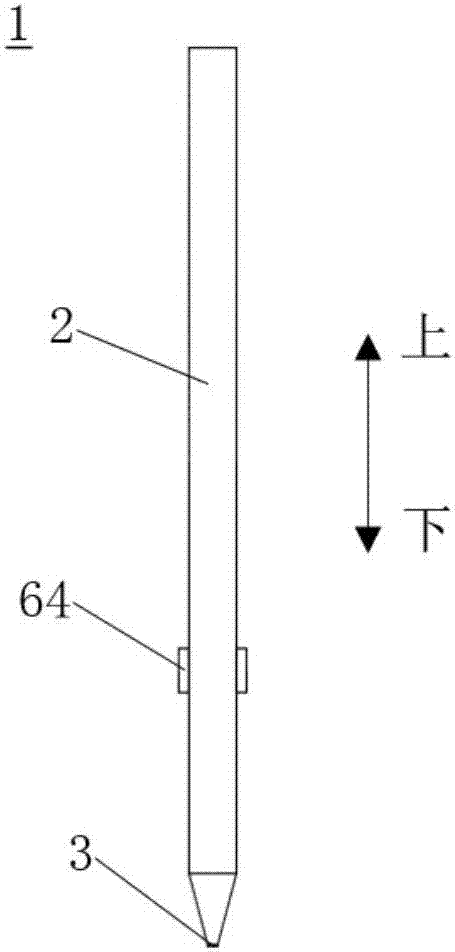
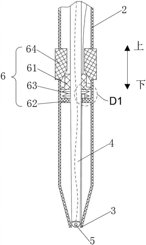
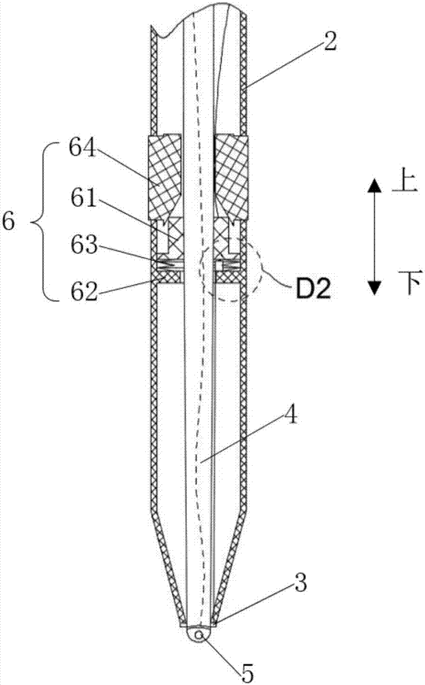
[0041] figure 1 It is a front view of the oral examination device 1 according to the embodiment of the present invention, figure 2 It is a partial cross-sectional view of the oral cavity inspection device 1 according to the embodiment of the present invention, the radial pressing block 64 in this figure is not pressed, image 3 It is a partial cross-sectional view of the oral cavity inspection device 1 according to the embodiment of the present invention, and the radial pressing block 64 in this figure has been pressed. Such a...


PUM


Abstract

The invention relates to an oral cavity examination apparatus, which comprises sleeves, a sliding rod, an image collection device and push rod mechanisms, wherein annular LED lamps are arranged on the end faces of the lower ends of the sleeves. Each of the push rod mechanisms comprises a sliding block, an annular flange, a compression spring and a radial pressing block, wherein an ejection inclined plane is formed in the lower part of the inner wall of each radial pressing block; the ejection inclined planes can abut against the upper parts of the sliding blocks; and by virtue of the ejection inclined planes, the sliding blocks are pushed to move towards the lower ends of the sleeves when the radial pressing blocks move inwards in a radial direction, so that the image collection device, which is hidden in the sleeves, is pushed out of an opening. Conductive blocks are arranged at the upper parts of the annular flanges in the axial directions of the compression springs; the conductive blocks are electrically connected to the LED lamps by virtue of lead wires; conductive needles are inserted in the sliding blocks in a vertical direction; the first end parts of the conductive needles extend out of the lower end faces of the sliding blocks and the second end parts of the conductive needles are connected to a power supply; and the first end parts get into contact with the conductive blocks when the compression springs are under a compressed state. The oral cavity examination apparatus is simple in structure and convenient to operate, and various parts in an oral cavity can be clearly observed conveniently.

Description

technical field [0001] The invention relates to a medical appliance, in particular to an oral cavity inspection device. Background technique [0002] Regular dental check-ups have different meanings for different people. For example, in childhood, caries and misaligned teeth are the main problems. Parents should take their children to have check-ups every six months; In some people's minds, the idea that toothache is not a disease still exists, so that caries and periodontal disease are allowed to develop. As a result, the life span of the tooth is much shorter than its life. Therefore, adults should have a dental check-up every year and clean it every six months. Primary teeth: In old age, the main problems are tooth loss and tooth restoration. Residual roots and crowns should be dealt with in time to prevent them from becoming lesions and causing damage to the heart, kidneys, and eyes. Therefore, the elderly should have oral examinations every six months. [0003] However...

Claims


Application Information

Patent Timeline
Patent Type & Authority Patents(China)
IPC IPC(8): A61B1/24A61B1/06A61B1/04
CPCA61B1/00009A61B1/00064A61B1/00131A61B1/04A61B1/0684A61B1/24
Inventor 代雪松
Owner 代雪松
Learn More