Cleaning device with clamping structure

A clamping structure and cleaning device technology, used in cleaning equipment, cleaning machinery, carpet cleaning, etc., can solve problems such as easy winding on cleaning strips or cleaning plates, inability to clean and separate, and inconvenient cleaning of the cleaning body.

Active Publication Date: 2016-10-26
陈思
View PDF5 Cites 3 Cited by
  • Summary
  • Abstract
  • Description
  • Claims
  • Application Information

AI Technical Summary

Problems solved by technology

[0002] Existing cleaning devices generally include three parts: a handle, a cleaning head, and a cleaning body. The cleaning body is divided into two types: a cleaning strip and a cleaning plate. However, since the dirt absorbed by the surface to be cleaned has different sizes and shapes, now Some two kinds of cleaning main bodies cannot effectively clean and separate them, such as long hair, etc., due to their own characteristics, it is easy to wrap around the cleaning strip or cleaning board, affecting the cleaning effect in the next step and causing cleaning problems. A lot of inconvenience when cleaning the main body
On the other hand, how to squeeze out the excess water on the cleaning body in time to ensure the cleaning effect is not the same, and the effect is not satisfactory.

Method used


Image

  • Cleaning device with clamping structure
  • Cleaning device with clamping structure

Examples


Embodiment Construction

[0021] The present invention will be further described in detail below in conjunction with the accompanying drawings, so that those skilled in the art can implement it with reference to the description.

[0022] It should be understood that terms such as "having", "comprising" and "including" as used herein do not entail the presence or addition of one or more other elements or combinations thereof.

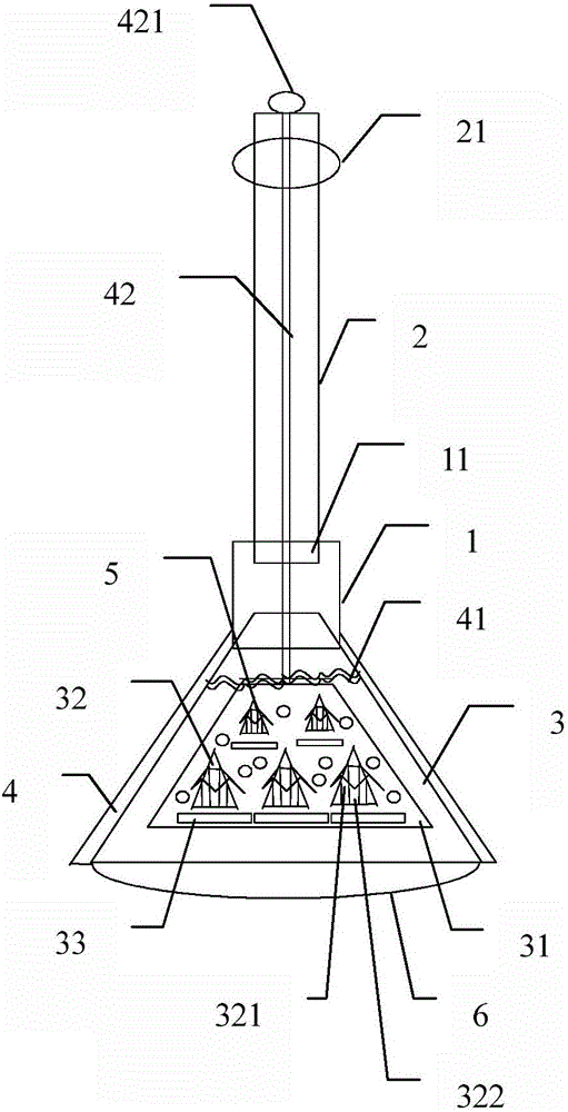
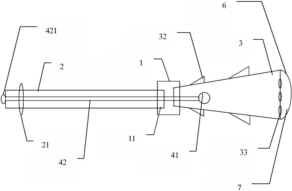
[0023] like Figures 1 to 2 As shown, the present invention provides a cleaning device with a clamping structure, comprising:

[0024] The cleaning head 1 is equipped with a handle 2 on its upper end, and an anti-slip layer 21 is arranged on the upper end of the handle, which is convenient for holding and feels good. The cleaning head is cylindrical, and the upper and lower ends of the column are provided with installation ports 11, and the handle is fixed in the installation ports at the upper end of the column.

[0025] The cleaning main body 3 is installed at the lower end o...


PUM


Abstract

The invention relates a cleaning device with a clamping structure. The cleaning device comprises the components of a cleaning head of which the upper end is provided with a handle; a cleaning body which is mounted at the lower end of the cleaning head and has a sector-shaped structure, wherein the cleaning body is internally provided with a first accommodating space, two side surfaces of the cleaning body are provided with a plurality of projections and holes, and the projections and the holes are separately arranged; a plurality of dirt separating structures, wherein each projection is provided with a dirt separating structure; a pair of clamping structures which are mounted on two side walls of the cleaning body, wherein a compression spring is mounted at the upper part of the pair of clamping structures, the middle part of the compression spring is provided with a drawing bar, the drawing bar successively penetrates through the upper end of the cleaning body, the cleaning head and the handle and furthermore is arranged at the end of the handle through a holding part; and an arc-shaped member which is mounted at the bottom surface of the big-head end of the cleaning body and furthermore clamps the big-head end of the cleaning body at the central part. The cleaning device performs functions of improving separation effect on dirt which is absorbed on the cleaning body, and furthermore eliminating redundant water which are absorbed on the cleaning body.

Description

technical field [0001] The invention relates to a cleaning device. More specifically, the present invention relates to a cleaning device having a holding structure. Background technique [0002] Existing cleaning devices generally include three parts: a handle, a cleaning head, and a cleaning body. The cleaning body is divided into two types: a cleaning strip and a cleaning plate. However, since the dirt absorbed by the surface to be cleaned has different sizes and shapes, now Some two kinds of cleaning main bodies cannot effectively clean and separate them, such as long hair, etc., due to their own characteristics, it is easy to wrap around the cleaning strip or cleaning board, affecting the cleaning effect in the next step and causing cleaning problems. A lot of inconvenience when cleaning the main body. On the other hand, how to squeeze out the excess water on the cleaning body in time to ensure the cleaning effect is not the same, and the effect is not satisfactory. ...

Claims


Application Information

Patent Timeline
Patent Type & Authority Applications(China)
IPC IPC(8): A47L13/10A47L13/42
CPCA47L13/10A47L13/42
Inventor 陈思
Owner 陈思
Why Eureka
Try Eureka