
Rubber powder feeding device

A technology of rubber powder and dust collection device, which is applied in transportation, packaging, loading/unloading, etc. It can solve the problems of personal insecurity, affecting the ratio of material and powder, and loud noise, so as to reduce air pollution, realize the output volume, The effect of small dust loss

Inactive Publication Date: 2016-10-19
天津滨海新区大港汇丰汽车装饰有限公司
View PDF0 Cites 2 Cited by
  • Summary
  • Abstract
  • Description
  • Claims
  • Application Information

AI Technical Summary

Problems solved by technology

[0002] In the production of rubber products, the rubber powder feeder is an indispensable production equipment. In the past, workers generally poured the powder into the hopper of the rubber product molding equipment manually. Due to the high temperature of the molding equipment , there are potential safety hazards, especially large-scale molding equipment needs to add a large amount of powder, if the entire process is operated manually, the efficiency will be low
Others use mechanical transmission, which is open, scattered in structure, large in size, pollutes the air in the production environment, and is not safe for people; if pneumatic suction or blowing is used, the noise is large, the power consumption is high, and the system and equipment are complicated. It is inconvenient to install and maintain. The shortage and fullness of the material in the hopper are all observed by human eyes, which increases the labor intensity of the operator and is not conducive to production automation.
At the same time, in the prior art, the rubber powder is easy to be damp and agglomerated during storage or production, which affects the proportion of the powder and directly affects the quality of the rubber product.

Method used


Image

  • Rubber powder feeding device
  • Rubber powder feeding device
  • Rubber powder feeding device

Examples


Embodiment Construction

[0023] It should be noted that, in the case of no conflict, the embodiments of the present invention and the features in the embodiments can be combined with each other.

[0024] Specific embodiments of the invention will be described in detail below in conjunction with the accompanying drawings.

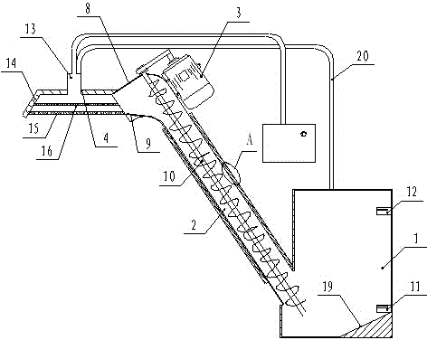
[0025] A rubber powder feeding device, such as figure 1 As shown, it includes the material height detection device installed in the material storage cylinder 1, the upper material cylinder 2, the motor 3, the dust suction device 4 and the storage cylinder 1; as figure 2 As shown, the cylinder wall of the upper material cylinder 2 is a hollow structure, including an inner wall 5 and an outer wall 6 on the outer side of the inner wall 5, a drying device is arranged between the inner wall 5 and the outer wall 6, and an insulating layer is arranged on the inner side of the outer wall 5 7; The upper end of the upper barrel 2 is provided with a blanking elbow 8, and its lower end extend...


PUM


Abstract

The invention provides a rubber powder feeding device, comprising a material holding cylinder, a feeding cylinder, a motor, a dust extraction device, and a material height detection device arranged in the material holding cylinder. The cylinder wall of the feeding cylinder is in a hollow structure, and comprises an inner wall and an outer wall on the outer side of the inner wall. A drying device is arranged between the inner wall and the outer wall. The inner side of the outer wall is provided with a thermal insulation layer. The upper end of the feeding cylinder is provided with a blanking elbow, and the lower end extends into the material holding cylinder. The outlet of the blanking elbow is provided with an adjusting plate. The motor drives a feeding shaft which is arranged in the feeding cylinder to rotate. The dust extraction device is arranged on the top end out of the outlet of the blanking elbow. The device is uniform in feeding, and easy in control, and is stable and reliable. The material height detection device can respectively give out alarm sound when feed powders in the material holding cylinder is not sufficient or excessive, and prompts operating personnel. The dust extraction device greatly reduces air pollution and reduces dust loss, and accurate matching of feed powders is easy to realize.

Description

technical field [0001] The invention belongs to the technical field of rubber equipment, in particular to a rubber powder feeding device. Background technique [0002] In the production of rubber products, the rubber powder feeder is an indispensable production equipment. In the past, workers generally poured the powder into the hopper of the rubber product molding equipment manually. Due to the high temperature of the molding equipment , there are potential safety hazards, especially large-scale molding equipment needs to add a large amount of powder, and the entire process is inefficient if it is manually operated. Others use mechanical transmission, which is open, scattered in structure, large in size, pollutes the air in the production environment, and is not safe for people; if pneumatic suction or blowing is used, the noise is large, the power consumption is high, and the system and equipment are complicated. It is inconvenient to install and maintain, and the shortag...

Claims


Application Information

Patent Timeline
Patent Type & Authority Applications(China)
IPC IPC(8): B65G65/38B65G69/18
Inventor 顾孟良
Owner 天津滨海新区大港汇丰汽车装饰有限公司
Learn More