Headrest moving device
A mobile device and headrest technology, which is applied in transportation and packaging, special positions of vehicles, stools, etc., can solve problems such as increased manufacturing costs and complex structures, and achieve minimum reduction in noise and durability, good durability, and The effect of enhancing functionality
- Summary
- Abstract
- Description
- Claims
- Application Information
AI Technical Summary
Problems solved by technology
Method used
Image
Examples
Embodiment approach 1
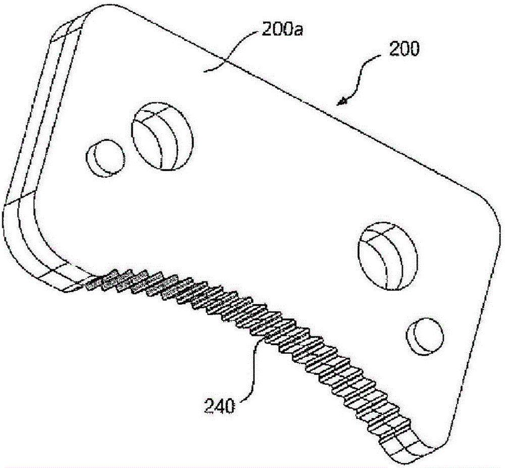
[0064] Such as Figures 1 to 10 As shown, the headrest moving device according to an exemplary embodiment of the present invention is characterized in that it includes: a ratchet 200; a pawl 100, which engages with the ratchet 200; and a lever 10, which is used to press the ratchet 100 And the engagement between the ratchet 100 and the ratchet 200 is disengaged, wherein one of the ratchet 100 and the ratchet 200 is connected to the seat, and the other is connected to the headrest, and the lever A member 10 is pivotally connected to the seat or the headrest.
[0065] The pawl 100 is vertically disposed in the front-rear direction, and is formed in a plate-like shape, and a plurality of gear teeth 150 are formed on an upper portion thereof in width and length directions.
[0066] The pawl 100 is formed by coupling in the width direction a plurality of plates 100a formed with a plurality of gear teeth 240 in the length direction, and thus, a plurality of gear teeth 150 are forme...
Embodiment approach 2
[0117] Different from the above Embodiment 1, such as Figures 12 to 20 As shown, the headrest moving device according to the second exemplary embodiment further includes: a first connecting member 300 connected to the seat; a second connecting member 400 mounted on the first connecting member in a pivotal state; 300 on one side; the third link 500, which is installed in the other side of the first link 300 in a pivoted state; and the fourth link 600, one end of which is installed in a pivoted state In the second connecting part 400, the other end is pivotally installed in the third connecting part 500, wherein the headrest is connected to the fourth connecting part 600; the pawl 100' is connected to to the first link 300 ; and the ratchet 200 ′ is connected to the second link 400 .
[0118] For the same configuration as the above-described embodiment, detailed description and illustration are omitted.
[0119] A stopper protrusion 170 is protrudingly formed in the pawl 100'...
PUM
 Abstract
Description
Claims
Application Information
 - R&D
- Intellectual Property
- Life Sciences
- Materials
- Tech Scout
- Unparalleled Data Quality
- Higher Quality Content
- 60% Fewer Hallucinations
Browse by: Latest US Patents, China's latest patents, Technical Efficacy Thesaurus, Application Domain, Technology Topic, Popular Technical Reports.
© 2025 PatSnap. All rights reserved.Legal|Privacy policy|Modern Slavery Act Transparency Statement|Sitemap|About US| Contact US: help@patsnap.com


