Multi-electrode sparking plug

A spark plug and multi-electrode technology, applied in the field of spark plugs, can solve problems such as difficulty in ensuring full combustion of fuel, generation of harmful gases, and high fuel consumption, and achieve the effects of reducing emissions, prolonging ignition time, and fully burning fuel

Inactive Publication Date: 2016-10-12
上海极燃汽车科技有限公司
View PDF5 Cites 4 Cited by
  • Summary
  • Abstract
  • Description
  • Claims
  • Application Information

AI Technical Summary

Problems solved by technology

[0002] The spark plug is a part of the gasoline engine ignition system that introduces high-voltage current into the cylinder to generate electric sparks to ignite the combustible gas mixture. At present, the common traditional automobile spark plug is composed of a metal shell, a ceramic insulator, a center electrode and a metal shell. Through the high-voltage ignition coil, the center The high-voltage discharge between the electrodes and the side electrodes generates sparks, which ignite the mixed gas fuel in the combustion chamber of the engine. The combustion of the mixed fuel pushes the piston to reciprocate, so that the crankshaft drives the engine to rotate. Generally, the spark plug only has one center electrode and one side electrode. It is easy to be damaged after use. In order to prolong the service life of the spark plug, the existing spark plug will be designed with multiple side electrodes, so that multiple side electrodes can be used in turn to prolong the service life. A spark plug with multiple side electrodes, when high-voltage discharge Only the side electrode closest to the center electrode will be selected to discharge to form an arc, that is to say, once the high-voltage ignition coil works, a spark plug can only ignite once. Since the high-voltage ignition coil works for a very short time, it is difficult to ensure the fuel Complete combustion, resulting in higher fuel consumption and possible production of harmful gases

Method used


Image

  • Multi-electrode sparking plug
  • Multi-electrode sparking plug
  • Multi-electrode sparking plug

Examples


Embodiment Construction

[0019] In describing the present invention, it is to be understood that the terms "center", "upper", "lower", "front", "rear", "left", "right", "vertical", "horizontal", The orientations or positional relationships indicated by "top", "bottom", "inner", "outer", etc. are based on the orientations or positional relationships shown in the drawings, and are only for the convenience of describing the present invention and simplifying the description, rather than indicating or implying References to devices or elements must have a particular orientation, be constructed, and operate in a particular orientation and therefore should not be construed as limiting the invention. In the description of the present invention, unless otherwise specified, "plurality" means two or more.

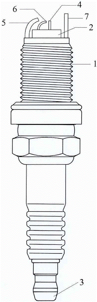
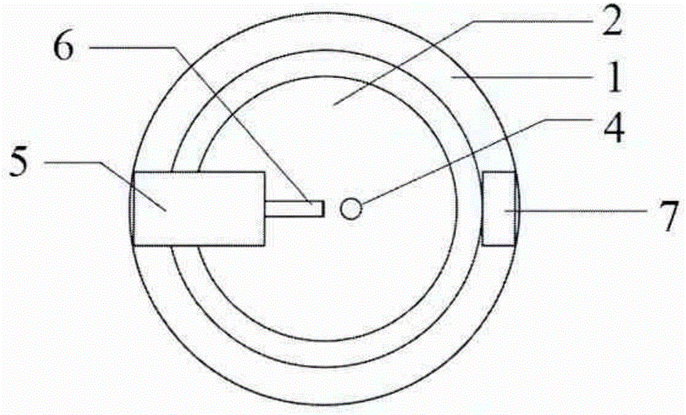
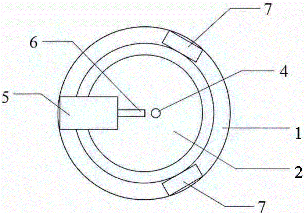
[0020] The present invention will be described in detail below in conjunction with accompanying drawing, as Figure 1 to Figure 3 As shown: the multi-electrode spark plug described in this embodiment include...


PUM


Abstract

The invention discloses a multi-electrode spark plug, comprising a metal shell, one end of the metal shell is provided with a ceramic insulator penetrating through the metal shell, a working side electrode and a guard electrode are provided, and the ceramic insulator passes through the metal shell One end of the ceramic insulator is provided with a wire nut, and the other end is provided with a center electrode and a suspension electrode. The center electrode and the wire nut are connected inside the ceramic insulator, and the ceramic insulator is provided with a suspension electrode. The suspension electrode is located between the center electrode and the side electrodes, and the metal shell, the center electrode and the side electrodes are not in contact with the suspension electrodes. The multi-electrode spark plug of the present invention can realize two ignitions, prolong the ignition time, make the fuel burn more fully, improve the efficiency of the engine, reduce harmful tail gas emissions, and reduce fuel consumption.

Description

technical field [0001] The invention relates to the technical field of spark plugs, in particular to a multi-electrode spark plug. Background technique [0002] The spark plug is a part of the gasoline engine ignition system that introduces high-voltage current into the cylinder to generate electric sparks to ignite the combustible gas mixture. At present, the common traditional automobile spark plug is composed of a metal shell, a ceramic insulator, a center electrode and a metal shell. Through the high-voltage ignition coil, the center The high-voltage discharge between the electrodes and the side electrodes generates sparks, which ignite the mixed gas fuel in the combustion chamber of the engine. The combustion of the mixed fuel pushes the piston to reciprocate, so that the crankshaft drives the engine to rotate. Generally, the spark plug only has one center electrode and one side electrode. It is easy to be damaged after use. In order to prolong the service life of the s...

Claims


Application Information

Patent Timeline
IPC IPC(8): H01T13/46H01T13/02
CPCH01T13/465H01T13/02
Inventor 王楠张孝亮
Owner 上海极燃汽车科技有限公司
Why Eureka
Try Eureka