
Winding head mechanism

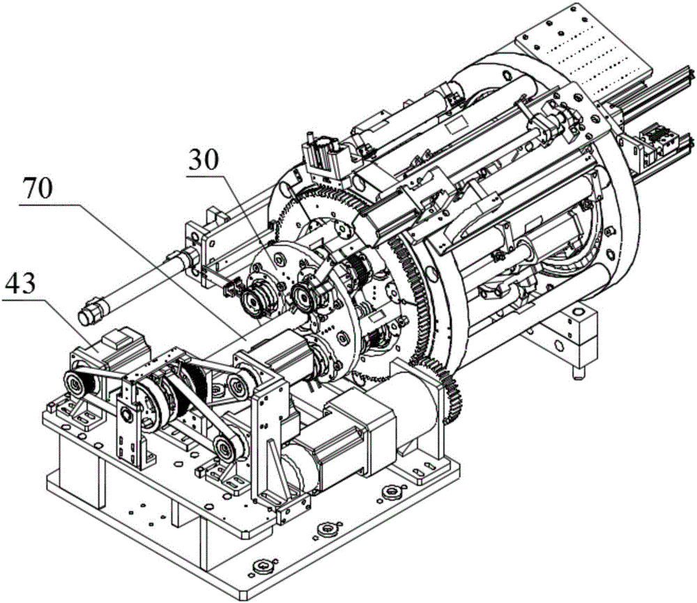
A winding head, follow-up technology, used in battery assembly, sustainable manufacturing/processing, climate sustainability, etc., can solve the problems of twisting, knotting, lag, and response lag of motor wires and signal wires, and reduce Equipment cost and production cost, the effect of improving winding quality and efficiency, and improving response speed

Active Publication Date: 2016-10-12
GEESUN AUTOMATION TECH
View PDF4 Cites 13 Cited by
  • Summary
  • Abstract
  • Description
  • Claims
  • Application Information

AI Technical Summary

Problems solved by technology

In this structure, when the winding motor 43 receives the signal to run, because there is a gap between the two stages of transmission, the state when it is driven to the winding needle and when the signal is given is delayed by the time of the two transmission gaps, resulting in a corresponding lag; at the same time Due to the cumulative transmission of the gap, the quality of the actual rolled-out battery core is also not good.
When making square cells, under high-speed conditions, rapid speed changes have higher requirements for transmission clearance and response time, and two-stage transmission is difficult to meet the requirements
[0005] To sum up, in the two-stage transmission method in the prior art, problems such as twisting and knotting of motor wires and signal wires will occur during the transmission process; at the same time, there are problems such as large cumulative error of transmission and lag in response. Especially in the case of winding square cells, it seriously affects the winding efficiency and winding quality

Method used


Image

  • Winding head mechanism
  • Winding head mechanism
  • Winding head mechanism

Examples


Embodiment Construction

[0025] Embodiments of the present invention are described in detail below, examples of which are shown in the drawings, wherein the same or similar reference numerals designate the same or similar elements or elements having the same or similar functions throughout. The embodiments described below by referring to the figures are exemplary and are intended to explain the present invention and should not be construed as limiting the present invention.

[0026] In describing the present invention, it should be understood that the terms "center", "longitudinal", "transverse", "length", "width", "thickness", "upper", "lower", "front", " The orientation or positional relationship indicated by "rear", "left", "right", "vertical", "horizontal", "top", "bottom", "inner" and "outer" are based on the orientation or position shown in the drawings The positional relationship is only for the convenience of describing the present invention and simplifying the description, but does not indica...


PUM


Abstract

The invention provides a winding head mechanism which comprises a base, a sliding ring, a following plate, a station change motor and at least one winding main body, wherein the sliding ring comprises a rotor and a stator which can rotate relatively; the stator is fixed on a limiting bracket; the following plate is fixedly connected with the rotor of the sliding ring, and can rotate relative to a main supporting part. According to the winding head mechanism provided by the invention, due to the rotatable matching between the rotor and the stator in the sliding ring, the problem that a cable is knotted in the prior art is solved; meanwhile, a winding motor is mounted on the following plate to directly drive a winding driving shaft to rotate and further drive a winding needle to work, so that a transmission gap and an error can be reduced; furthermore, the response speed can be greatly increased, and the winding quality and the efficiency are improved; moreover, speeding up of variable rotating speed control is facilitated, so that the production efficiency is greatly improved, and the equipment cost and the production cost are reduced.

Description

technical field [0001] The invention relates to a winding machine used in the manufacture of lithium battery core packs, in particular to a winding head mechanism. Background technique [0002] In the field of winding machines for making lithium battery core packs, in the prior art, the winding heads used by multi-station winding machines such as double-station or three-station evenly distribute each station in a cylindrical area ; The switching of each station is realized through the rotation of the cylindrical area, and the winding of each station also needs to be able to realize functions such as rotation and positioning independently. [0003] Under this scheme, during the station switching process, the drive system that realizes the rotation and positioning of each station will have related cables. If the drive system rotates following the station switch, the cables of each station will be knotted and broken. Case. In the prior art, multi-station winding motors usuall...

Claims


Application Information

Patent Timeline
Patent Type & Authority Applications(China)
IPC IPC(8): H01M10/04H01M10/052H01M10/058
CPCH01M10/0409H01M10/052H01M10/058Y02E60/10Y02P70/50
Inventor 张明李立鹏阳如坤魏宏生
Owner GEESUN AUTOMATION TECH
Learn More