Crystal grain moving clamp

A technology for moving fixtures and dies, applied in electrical components, semiconductor/solid-state device manufacturing, circuits, etc., can solve the problems of easy drop of die, drop of die yield, inaccurate control of die, etc., and achieve firm fixation. , The effect of high grasping accuracy and not easy to fall

Inactive Publication Date: 2016-10-12
WUXI HI NANO TECH
View PDF5 Cites 2 Cited by
  • Summary
  • Abstract
  • Description
  • Claims
  • Application Information

AI Technical Summary

Problems solved by technology

However, in this method, the die is easy to drop, resulting in a decrease in the yield of the die
And this method is inaccurate for the control of the grain

Method used


Image

  • Crystal grain moving clamp

Examples


Embodiment Construction

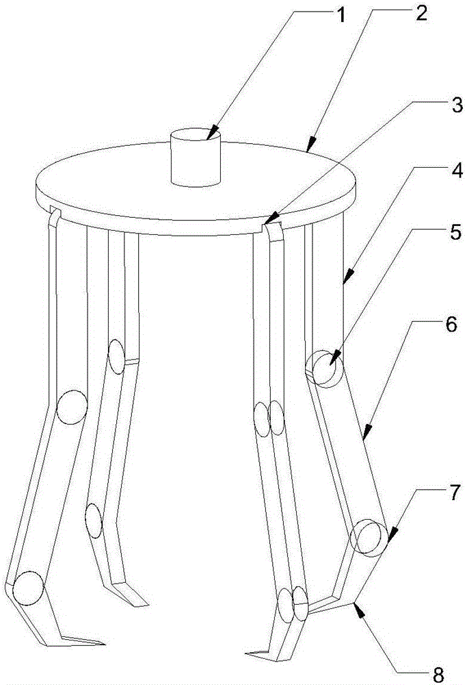
[0009] figure 1 is a schematic diagram of the present invention. The invention includes a motor control lever 1 . The lower end of the motor control rod 1 is fixed with a disc-shaped clamp fixing disc 2 . A plurality of mounting grooves 3 with equal intervals are provided on the edge of the lower surface of the fixture fixing plate 2 . Also includes multiple sets of jig jaws. Each set of clamp jaws includes a first arm 4 fixed on the mounting groove 3 . The end of the first arm 4 is installed with the second arm 6 and the second arm 6 can rotate around the end of the first arm 4 relative to the first shaft 5 . A third arm 8 is installed at the end of the second arm 6 and the third arm 8 can rotate around the end of the second arm 6 relative to the second shaft 7 . The end of the third arm 8 is a flat structure, and the end of the flat structure is a tip.

[0010] The invention can be used in cooperation with the motor unit. Each set of gripper jaws is equipped with a se...


PUM


Abstract

The invention discloses a crystal grain moving clamp, which comprises a motor control rod. The lower end of the motor control rod is fixed with a disc-shaped clamp fixing disc; and multiple equidistant mounting grooves are arranged at edges of the lower surface of the clamp fixing disc. The crystal grain moving clamp also comprises clamp claws. Each clamp claw comprises a first arm rod fixed above the mounting groove; the tail end of the first arm rod is provided with a second arm rod and the second arm rod can rotate around the tail end of the first arm rod relative to a first axis; the tail end of the second arm rod is provided with a third arm rod and the third arm rod can rotate around the tail end of the second arm rod relative to a second axis; and the tail end of the third arm rod has a flat structure, and the tail end of the flat structure is a sharp end. According to the crystal grain moving clamp disclosed by the invention, through a matched motor group, the clamp can flexibly grasp a crystal grain with a small area and thin thickness, the grasping accuracy is high, the crystal grain is firmly fixed after being grasped, and the crystal grain is likely to fall.

Description

technical field [0001] The invention relates to semiconductor packaging and testing, in particular to a crystal grain moving fixture. Background technique [0002] During the process of semiconductor packaging, it is necessary to move the die. In the prior art, sticky grippers are mostly used to move the crystal grains, and the grains are adsorbed on the grippers for a short period of time. However, in this method, the crystal grains are easy to drop, resulting in a decrease in the yield of the crystal grains. And this kind of method is imprecise to the control of grain. Contents of the invention [0003] Aiming at the deficiencies of the prior art, the invention discloses a grain moving jig. [0004] Technical scheme of the present invention is as follows: [0005] A crystal grain moving fixture, comprising a motor control rod; the lower end of the motor control rod is fixed with a wafer-shaped fixture fixing plate; the edge of the lower surface of the fixture fixing ...

Claims


Application Information

Patent Timeline
Patent Type & Authority Applications(China)
IPC IPC(8): H01L21/687
CPCH01L21/687
Inventor 吕耀安
Owner WUXI HI NANO TECH
Why Eureka
Try Eureka