A transformer lamination assembly tooling

A transformer and lamination technology, applied in the field of transformers, can solve the problems of large joints, low production efficiency, high cost, etc., and achieve the effects of uniform fastening force, high production efficiency and convenient operation

Active Publication Date: 2018-01-26
SUZHOU WUBIAN ELECTRICAL TECH CO LTD
View PDF5 Cites 0 Cited by
  • Summary
  • Abstract
  • Description
  • Claims
  • Application Information

AI Technical Summary

Problems solved by technology

[0002] For silicon steel laminations of transformers, the lamination tooling used in the existing lamination method is not only very expensive but also complicated to operate, high in cost, and low in production efficiency. The formed lamination structure cannot meet the requirements. There are large seams in

Method used


Image

  • A transformer lamination assembly tooling

Examples


Embodiment Construction

[0009] The preferred embodiments of the present invention will be described in detail below in conjunction with the accompanying drawings, so that the advantages and features of the present invention can be more easily understood by those skilled in the art, so as to define the protection scope of the present invention more clearly.

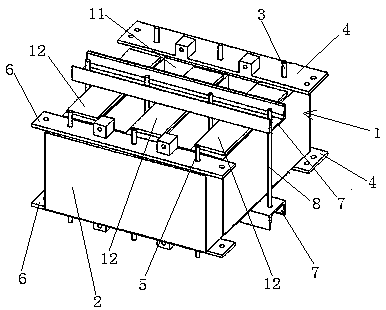
[0010] like figure 1 As shown, a transformer lamination assembly tooling includes a set of mountain-shaped laminations 1 and a set of upper iron yoke laminations 2. The mountain-shaped laminations 1 have a lower iron yoke 11 and three vertically arranged on the lower iron yoke 11. A core column part 12, the mountain-shaped lamination 1 is made of several mountain-shaped silicon steel sheets, and the upper iron yoke laminate 2 is made of several strip-shaped silicon steel sheets. On the three core column parts 12, the upper iron yoke laminations 2 and the mountain-shaped laminations 1 form a closed structure, and the lower iron yoke part 11 of the...


PUM


Abstract

The invention discloses a laminated combination tooling for a transformer. The laminated combination tooling comprises a group of mountain-shaped stacks and a group of upper iron yoke stacks; the mountain-shaped stacks are provided with a lower iron yoke part and three stem parts; the upper iron yoke stacks are arranged on the three stem parts of the mountain-shaped stacks; the upper iron yoke stacks and the mountain-shaped stacks form closed structures; first positioning steel poles are arranged in the lower iron yoke parts of the mountain-shaped stacks in a penetrating manner; first positioning sheets are respectively arranged at the front side and the rear side of the lower iron yoke part; the end parts of the first positioning steel poles penetrate through the first positioning sheets; second positioning steel poles are arranged in the upper iron yoke stacks in a penetrating manner; second positioning sheets are respectively arranged at the front and rear sides of the upper iron yoke stacks; the end parts of the second positioning steel poles penetrate through the second positioning sheets; one clamping channel steel crossing over the three stem parts is arranged on each of the front and rear sides of the mountain-shaped stacks; the two clamping channel steels are connected by screws. The laminated combination tooling disclosed by the invention has the advantages of higher convenience in operation, time saving, labor saving, cost saving and high production efficiency; in addition, the formed laminated structure meets the requirements and no joints are generated.

Description

technical field [0001] The invention relates to the technical field of transformers, in particular to a transformer lamination assembly tooling. Background technique [0002] For silicon steel laminations of transformers, the lamination tooling used in the existing lamination method is not only very expensive but also complicated to operate, high in cost, and low in production efficiency. The formed lamination structure cannot meet the requirements. There are large seams in . Contents of the invention [0003] In order to solve the above technical problems, the object of the present invention is to provide a transformer lamination assembly tool, which is not only easy to operate, low in cost, but also has no seams. [0004] In order to achieve the above-mentioned technical purpose and achieve the above-mentioned technical effect, the present invention is realized through the following technical solutions: a transformer lamination assembly tooling, including a set of mount...

Claims


Application Information

Patent Timeline
Patent Type & Authority Patents(China)
IPC IPC(8): H01F41/02H01F27/245
CPCH01F27/245H01F41/0233
Inventor 宋小路潘向南
Owner SUZHOU WUBIAN ELECTRICAL TECH CO LTD
Why Eureka
Try Eureka