Three-span anti-node beam-transverse wave-three steel-concrete composite T-shaped continuous beam

A three-steel concrete and antinode technology, which is applied to bridges, bridge construction, erection/assembly of bridges, etc., can solve the problems of high production requirements and uneconomical use of ultra-high performance concrete, and achieve material saving, cost reduction, and increased The effect of lateral stability

Active Publication Date: 2017-08-25
HUNAN LIANZHI BRIDGE & TUNNEL TECH +2
View PDF3 Cites 0 Cited by
  • Summary
  • Abstract
  • Description
  • Claims
  • Application Information

AI Technical Summary

Problems solved by technology

[0013] In addition, Chinese patent 201420811093.1 proposed a two-dimensional corrugated steel and concrete composite bridge deck in 2014. The bridge deck (roof) of this patent is composed of ultra-high performance concrete (RPC for short) and a transverse corrugated steel floor. The bottom surface of the steel base plate is fixedly welded with a vertical corrugated steel web perpendicular to the horizontal corrugated steel plate, and the bottom of the vertical corrugated steel web is fixedly connected with the horizontal bottom plate, and the vertical corrugated steel web and the transverse corrugated steel plate form a corrugated beam structure, RPC is poured on the horizontal corrugated steel bottom plate to form a two-dimensional corrugated steel and RPC composite bridge deck. In this scheme, the horizontal corrugated steel bottom plate and the vertical corrugated steel web are welded to ensure the structural integrity. To: Compared with the orthotropic steel plate, its longitudinal span and transverse spacing are increased by 2 to 3 times, so that the number of orthogonal ribs can be reduced by 4 to 9 times, that is, the number of welds is reduced, and the Structural durability, reducing the probability of fatigue damage, but due to the high production requirements of ultra-high performance concrete (RPC), the cost is as high as 30,000 yuan / cubic meter, and it is uneconomical to use in general viaducts, thus limiting the promotion

Method used


Image

  • Three-span anti-node beam-transverse wave-three steel-concrete composite T-shaped continuous beam
  • Three-span anti-node beam-transverse wave-three steel-concrete composite T-shaped continuous beam
  • Three-span anti-node beam-transverse wave-three steel-concrete composite T-shaped continuous beam

Examples


Embodiment Construction

[0048] The embodiments of the present invention will be described in detail below with reference to the accompanying drawings, but the present invention can be implemented in various ways defined and covered by the claims.

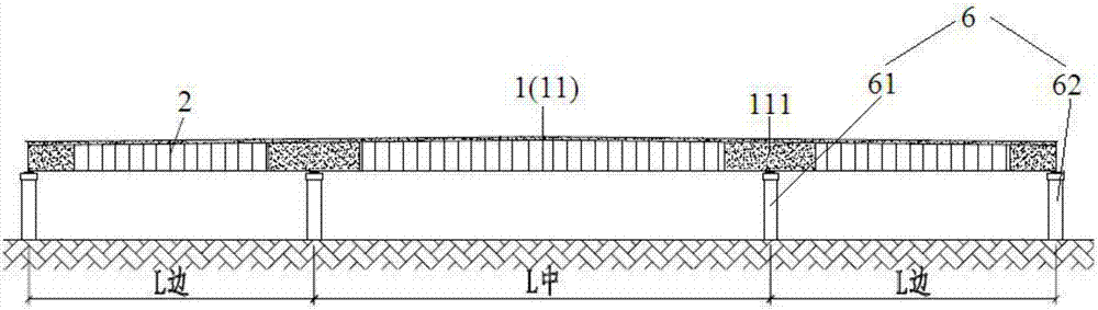
[0049] see figure 1 A kind of three-span antinode engineering beam-transverse wave-three steel concrete composite T-shaped continuous beam of ~Fig. 7:

[0050] In this embodiment, the mid-span span L 中 is 60m, the span L of the two side spans 边 Both are 35m.

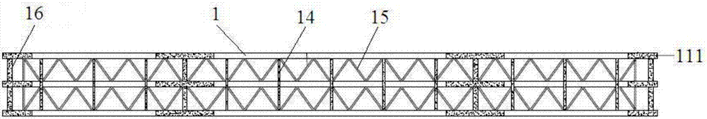
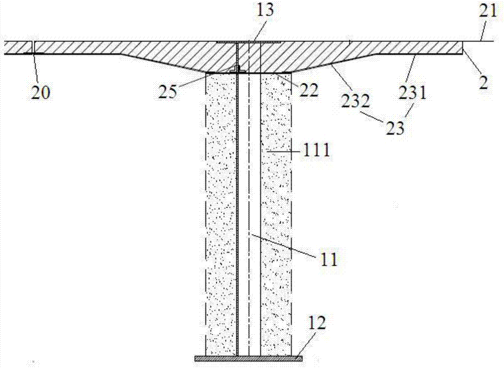
[0051] The main girder includes antinode beam 1, steel cross brace 14, steel diagonal brace 15 and concrete diaphragm 16. The wavelength on the corrugated steel web 11 is 160cm, the thickness of the corrugated steel plate is 1.4cm, and the wave height is 22cm. Plate 13 is 2.0cm thick and 60cm wide, and the lower flange plate 12 is 5.0cm thick and 100cm wide. At the bottom of every two antinode beams 1, welded H-shaped steel is used as cross brace 14 and diagonal brace 15, with a width of 30cm and ...


PUM


Abstract

The invention relates to a three-span antinode I-shaped beam-transverse wave-three-steel and concrete combined T-shaped continuous beam which comprises an antinode I-shaped beam (1) and a steel concrete combined top plate (2). A bridge span has a three-span continuous beam structure, and the setting of camber is not required. The invention firstly discloses an upper flange plate and a lower flange plate of the antinode I-shaped beam and are respectively parallel and level to a top plate and a bottom plate of the beam; the function of an antinode I-shaped beam reinforcing framework is fully utilized; temporary facilities used for pouring concrete on the top plate and the bottom plate are simplified; and concrete reinforcing bars are wrapped on the corrugated steel webs on the position of a supporting base along the length direction of a bridge and the thickness directions on the two sides, so that the maximum crushing stress of the lower edge of the section of the continuous beam supporting base is reduced, the buckling of the corrugated steel lower flange plate under the crushing stress is improved, and the diffusion of the concentrated force on the supporting base is benefited. The T-shaped continuous beam provided by the invention is high in construction speed and high in bearing capacity, requires no tensioning pre-stress, and is especially suitable for urban flyovers and engineering under strictly controlled under-bridge interference and tense working periods.

Description

technical field [0001] The present invention relates to two new materials of corrugated steel plate and three-steel concrete, and a new process for assembling and pushing continuous beams. In the field of bridges, they are integrated to form antinode beams (CS.W.IB) and three-steel concrete (SF. F.RC) roof composite continuous beam new structure, also referred to as double-wave SF.F.RC composite T-shaped continuous beam. Background technique [0002] This patent aims to propose a new type of urban viaduct type. In order to illustrate the purpose of this patent, from the application of urban viaducts, the shortcomings of conventional prestressed concrete girder bridges and steel box girder bridges, corrugated steel web beams and three-steel The advantages of concrete composite structures are discussed. [0003] 1. Urban Viaduct [0004] With the development of economy, my country's urbanization process has made great achievements. At the same time, higher requirements are ...

Claims


Application Information

Patent Timeline
Patent Type & Authority Patents(China)
IPC IPC(8): E01D2/00E01D21/00
CPCE01D2/00E01D21/00
Inventor 梁晓东项超群上官兴胡红波孙天明卢国林谢鸿吴加云易诞
Owner HUNAN LIANZHI BRIDGE & TUNNEL TECH
Why Eureka
Try Eureka