
A boring bar device for deep hole machining

A boring bar and deep hole technology, which is applied to boring bars, metal processing equipment, manufacturing tools, etc., can solve the problems of restricting the processing quality and processing efficiency of deep holes, the spindle cannot be directly processed, and the processing accuracy is reduced, etc., and achieves a simple structure. , Reduce the natural flexibility, improve the effect of supporting rigidity

Active Publication Date: 2017-12-08
常州市邦威机械有限公司
View PDF6 Cites 0 Cited by
  • Summary
  • Abstract
  • Description
  • Claims
  • Application Information

AI Technical Summary

Problems solved by technology

Deep holes inside large components, such as guide post holes on large molds, ram inner holes of machine tools, inner holes of box bodies, etc., cannot be processed directly by the spindle
In the existing processing methods, super long overhanging tools are mostly used for boring processing, and the boring bar is in an overhanging state, which can easily cause insufficient rigidity of the boring bar and cause vibration; when the centerline of the machine tool spindle and the centerline of the guide bushing When there is a deviation or a deflection angle, it will inevitably cause a decrease in machining accuracy. These unfavorable factors have greatly restricted the processing quality and processing efficiency of deep holes.

Method used


Image

  • A boring bar device for deep hole machining
  • A boring bar device for deep hole machining
  • A boring bar device for deep hole machining

Examples


Embodiment Construction

[0024] Below in conjunction with the preferred embodiment shown in accompanying drawing, be described in further detail:

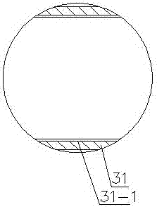
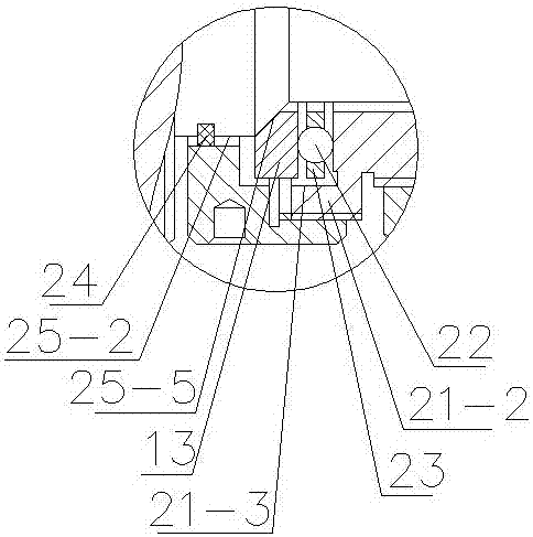
[0025] In Example 1, see Figure 1 ~ Figure 3 , a boring bar device for deep hole machining, installed on a boring machine, including a boring bar floating chuck device, the boring bar floating chuck device includes a socket shaft 25, a threaded cover 12, and a tube coaxial with the socket shaft 25 Shaped tail handle 21, coaxially sleeved on the connecting sleeve 16 on the outer peripheral surface of the tail handle 21, and the connecting sleeve 16 is coaxially installed on the boring machine main shaft.

[0026] Sleeve shaft 25 comprises shaft diameter successively decreasing and coaxial shaft section one 25-1, shaft section two 25-2, shaft section three 25-3, and one end of shaft section one 25-1 is provided with coaxial sleeve Hole 25-4, the head of the boring bar 1 is coaxially fitted in the sleeve hole 25-4, the boring bar 1 and the sleeve shaft 25 a...


PUM


Abstract

The invention relates to a boring bar device for deep hole processing. The boring bar device for deep hole processing comprises a boring bar floating chuck device, a boring bar supporting and guiding device and a boring cutter mounting hole, wherein the boring cutter mounting hole is formed in a boring bar and is used for mounting a boring cutter; an included angle is formed between the radial direction of the boring bar and the boring cutter mounting hole; the floating chuck device comprises a connecting sleeve shaft, a threaded cover, a barrel-shaped tail handle and a connecting sleeve; the barrel-shaped tail handle is coaxial with the connecting sleeve shaft; the connecting sleeve coaxially sleeves the surface of the outer circumference of the tail handle; the connecting sleeve is coaxially mounted on a spindle of a boring machine; the supporting and guiding device comprises an inner bushing, a sleeve and a guide bushing; the inner bushing sleeves the surface in the circumferential direction of the boring bar; the sleeve sleeves the surface of the outer circumference of the inner bushing; and the guide bushing is in clearance fit to the surface of the outer circumference of the sleeve and is fixed on the boring machine. By the floating chuck device, the boring bar can slightly float; and by the supporting and guiding device, the elongation of the boring bar can be increased, natural flexibility of the boring bar is reduced, and the supporting rigidity of the boring bar device is improved. The boring bar device for deep hole processing is simple in structure, good in rigidity, flexible in operation and convenient to maintain, and is suitable for deep hole boring of the inside of a large part; and quality, reliability and efficiency of deep hole processing can be improved.

Description

technical field [0001] The invention relates to a boring bar device for deep hole processing, which belongs to the technical field of mechanical processing. Background technique [0002] In mass production and manufacturing, high-precision boring is an important means of hole finishing. Deep holes inside large components, such as guide post holes on large molds, ram inner holes of machine tools, inner holes of box bodies, etc., cannot be processed directly by the spindle. In the existing processing methods, super long overhanging tools are mostly used for boring processing, and the boring bar is in an overhanging state, which can easily cause insufficient rigidity of the boring bar and cause vibration; when the centerline of the machine tool spindle and the centerline of the guide bushing When there is a deviation or a deflection angle, it will inevitably cause a decrease in machining accuracy. These unfavorable factors have greatly restricted the processing quality and pro...

Claims


Application Information

Patent Timeline
Patent Type & Authority Patents(China)
IPC IPC(8): B23B41/02B23B29/02
CPCB23B29/022B23B41/02
Inventor 宋巧莲吴斌
Owner 常州市邦威机械有限公司
Learn More