
Mixing device based on improvement of moving convenience

A technology of mixing equipment and convenience, applied in the field of petroleum machinery auxiliary tools, can solve the problems of inconvenient movement and bottom damage, and achieve the effects of improving convenience, avoiding deformation and damage, and facilitating disassembly and installation.

Inactive Publication Date: 2016-10-12
CHENGDU DAMO PETROLEUM TECH CO LTD
View PDF4 Cites 0 Cited by
  • Summary
  • Abstract
  • Description
  • Claims
  • Application Information

AI Technical Summary

Problems solved by technology

[0005] The purpose of the present invention is to provide a mixing device based on improving the convenience of movement, so as to solve the problem that the existing stirring device is easy to cause damage to the bottom and is not easy to move

Method used


Image

  • Mixing device based on improvement of moving convenience

Examples


Embodiment 1

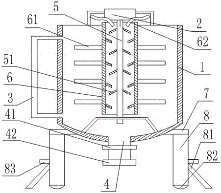
[0030] Such as figure 1 As shown, the mixing equipment based on improving the convenience of movement includes two fixed columns 8, on which a fixed plate 7 is arranged, and the middle part of the fixed plate 7 is provided with a circular through hole, and the tank body 1 passes through the circular through hole Fixed on the fixed plate 7, the bottom of the tank body 1 is provided with a discharge pipe 4, the discharge pipe 4 is provided with a valve 41, the top of the tank body 1 is provided with a motor 2, and the power output end of the motor 2 is connected with a rotating shaft 5, The rotating shaft 5 is arranged inside the tank body 1, and the rotating shaft 5 is connected to the cylinder body 6 through a connecting rod. An annular space is formed between the rotating shaft 5 and the cylinder body 6, and a feeding port 62 is arranged in the annular space, and a stirring device is provided on the outer wall of the cylinder body 6. The blades 61, the inner wall of the barre...

Embodiment 2

[0032] Such as figure 1 As shown, this embodiment is based on Embodiment 1, the side wall of the tank body 1 is provided with a bypass pipe 3, and the two ends of the bypass pipe 3 communicate with the upper end and the lower end of the tank body 1 respectively, and the bypass pipe 3 Made of transparent material; the outlet end of the discharge pipe 4 is provided with a joint 42; the side wall of the fixed column 8 is provided with a limit plate 83 that cooperates with the support plate 81; the inclined plate on the cylinder 6 51 is opposite to the direction of inclination of the swash plate 51 on the rotating shaft 5 .


PUM


Abstract

The invention discloses a mixing device based on improvement of moving convenience, wherein the mixing device at least includes 2 fixed columns; the fixed columns are provided with a fixed plate; the center of the fixed plate is provided with a circular through hole; a tank body passes through the circular through hole and is fixed on the fixed plate, and the bottom of the tank body is provided with a discharge pipe; the discharge pipe is provided with a valve; the top end of the tank body is provided with a motor; a power output end of the motor is connected with a rotating shaft; the rotating shaft is arranged inside the tank body and is connected with a cylinder body through a connecting rod, and an annular space is formed between the rotating shaft and the cylinder body and is provided with a feed inlet; the outer wall of the cylinder body is provided with stirring blades; the inner wall of the cylinder body and the outer wall of the rotating shaft are each provided with a plurality of inclined plates; the bottoms of the fixed columns are provided with idler wheels, and the side walls of the fixed columns are hinged with supporting plates. The problems that a conventional stirring device has the bottom easy to damage and is not convenient to move are solved.

Description

technical field [0001] The invention relates to the technical field of auxiliary tools for petroleum machinery, in particular to a mixing device based on improving the convenience of movement. Background technique [0002] In the process of oil extraction, with the development and use of oil wells, the surface gathering and transportation pipelines of oil wells and downhole production strings are corroded to varying degrees, and the frequency of pipeline corrosion and perforation events is increasing year by year. Carry out dosing and anticorrosion. Because the effectiveness of preservatives will weaken over time, it is necessary to refill preservatives every once in a while for adding preservatives to a single well. [0003] The injection of preservatives is handled by the dosing device. Before the preservatives are injected into the dosing device, the liquid medicine needs to be prepared (mixing different proportions of reagents to make preservatives). In order to ensure ...

Claims


Application Information

Patent Timeline
IPC IPC(8): B01F13/10B01F13/00B01F15/00
CPCB01F33/501B01F33/82B01F35/211
Inventor 贺昶明
Owner CHENGDU DAMO PETROLEUM TECH CO LTD
Learn More