
Cardiology chest cavity monitoring device

A monitoring device and cardiology technology, applied in the field of medical devices, can solve problems affecting test results, life-threatening, cross-infection, etc., and achieve the effect of improving treatment effect, reducing labor intensity, and convenient and quick access

Inactive Publication Date: 2018-12-21
侯勃 +1
View PDF6 Cites 0 Cited by
  • Summary
  • Abstract
  • Description
  • Claims
  • Application Information

AI Technical Summary

Problems solved by technology

[0002] Cardiovascular patients often have dyspnea. Due to the inability of the heart to transfuse blood and indirect non-rhythmic blood transfusion, it is easy to cause arrhythmia and sudden death. During the recovery treatment of cardiovascular patients, it is necessary to carry out continuous detection and treatment of patients to prevent Death due to respiratory interruption. The chest cavity monitoring device in the Department of Cardiology in the past can only analyze the respiratory rate alone, but cannot specifically analyze the heart activity in the patient's chest cavity, which will affect the test results. If oxygen rescue cannot be performed in time, it will cause life-threatening. , which greatly increases the work difficulty of medical staff. At the same time, in order to avoid cross-infection of diseases, an independent oxygen mask should be used for each patient. Since the rescue of patients in cardiovascular medicine needs to be carried out quickly, the chest cavity monitoring device in the cardiology department needs to be able to Quick access storage for oxygen masks

Method used


Image

  • Cardiology chest cavity monitoring device
  • Cardiology chest cavity monitoring device

Examples


Embodiment

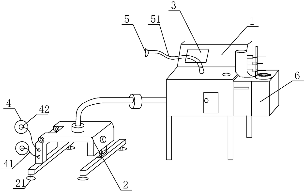
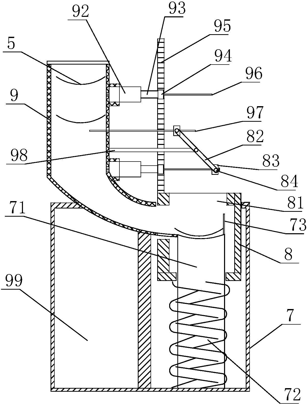
[0030] A chest monitoring device for cardiology, comprising a cabinet 1 and a chest fixing bracket 2, the cabinet 1 is provided with a power plug, the power plug is connected to an adapter, and the cabinet 1 is provided with a control device, an electrocardiogram machine, and an oxygen tank. The control device is provided with a central processing unit, and the electrocardiograph is connected to the display screen 3, which is convenient for medical personnel to observe the patient's electrocardiogram measurement results. The lower side of the chest cavity fixing bracket 2 is provided with a fixed suction cup 21 for fixing the fixing bracket on the bed body. The chest cavity fixing bracket 2 is provided with an induction line 41, the induction line 41 is connected to the chest cavity patch 4, the chest cavity patch 4 is provided with a data collector 42, and the inside of the chest cavity fixing bracket 2 is provided with a pressure sensor, The pressure sensor and the data coll...


PUM


Abstract

The invention discloses a thoracic cavity monitoring device for the department of cardiology. The thoracic cavity monitoring device comprises an equipment cabinet and a thoracic cavity fixing bracket, the equipment cabinet is internally provided with a control device, an electrocardiograph and an oxygen tank, the control device is provided with a central processing unit, and the electrocardiograph is connected with a display screen; the thoracic cavity monitoring device further includes an oxygen mask storage device, the oxygen mask storage device comprises a shell, the shell is internally provided with a movable sleeve in a sleevingmode, the movable sleeve is internally provided with a supporting pillar in a sleeving mode, after the movable sleeve is pressed downwards, the supporting pillar can stretch out of the movable sleeve through an opening, and the top end of the shell is provided with an oxygen mask storage barrel. The thoracic cavity monitoring device has the advantages that the device is convenient to use, oxygen can be supplied to patients with severe heart disease in time when the patients are attacked by the disease and lie in bed, and therefore accidents are avoided; the oxygen mask storage device can maintain cleanliness of an oxygen mask, the oxygen mask can also be taken rapidly, therefore, labor intensity of medical staff is lowered, and meanwhile the treatment effect of the patients is improved.

Description

technical field [0001] The invention mainly relates to the field of medical equipment, in particular to a chest cavity monitoring device in the Department of Cardiology. Background technique [0002] Cardiovascular patients often have dyspnea. Due to the inability of the heart to transfuse blood and indirect non-rhythmic blood transfusion, it is easy to cause arrhythmia and sudden death. During the recovery treatment of cardiovascular patients, it is necessary to carry out continuous detection and treatment of patients to prevent Death due to respiratory interruption. The chest cavity monitoring device in the Department of Cardiology in the past can only analyze the respiratory rate alone, but cannot specifically analyze the heart activity in the patient's chest cavity, which will affect the test results. If oxygen rescue cannot be performed in time, it will cause life-threatening. , which greatly increases the work difficulty of medical staff. At the same time, in order to ...

Claims


Application Information

Patent Timeline
Patent Type & Authority Patents(China)
IPC IPC(8): A61B5/03A61B5/0402A61M16/00
CPCA61B5/03A61M16/00A61M2202/0208A61M2205/3331A61M2230/04A61M16/0003A61B5/318A61M2230/005A61M2202/0007
Inventor 侯勃刘璞
Owner 侯勃
Learn More