An air-cooled turbogenerator wind path structure

A steam turbine generator and air path technology, applied in the magnetic circuit shape/style/structure, cooling/ventilation device, electromechanical device, etc., can solve the problem of excessive rotor temperature rise, brush carbon powder floating around, and pollution of the operating environment, etc. problem, to achieve the effect of uniform cooling

Active Publication Date: 2018-06-26
SHANDONG QILU ELECTRIC MOTOR MFG
View PDF6 Cites 0 Cited by
  • Summary
  • Abstract
  • Description
  • Claims
  • Application Information

AI Technical Summary

Problems solved by technology

[0002] With the continuous increase of the capacity of QF turbogenerators above 30MW, the stator and rotor are more slender and the heat is not easy to dissipate. The need for ventilation and cooling, the temperature rise of the rotor in the electromagnetic calculation exceeds the standard, which requires an air path structure to reduce the temperature rise of the rotor
The brushes and collector rings of the original QF turbogenerator are directly exposed in the air. The disadvantages are that the generator operating environment is noisy, which affects the operator and the surrounding environment, and the brush carbon powder generated by friction is scattered around. pollute the operating environment, and even affect the safe and normal operation of the generator

Method used


Image

  • An air-cooled turbogenerator wind path structure
  • An air-cooled turbogenerator wind path structure
  • An air-cooled turbogenerator wind path structure

Examples


Embodiment Construction

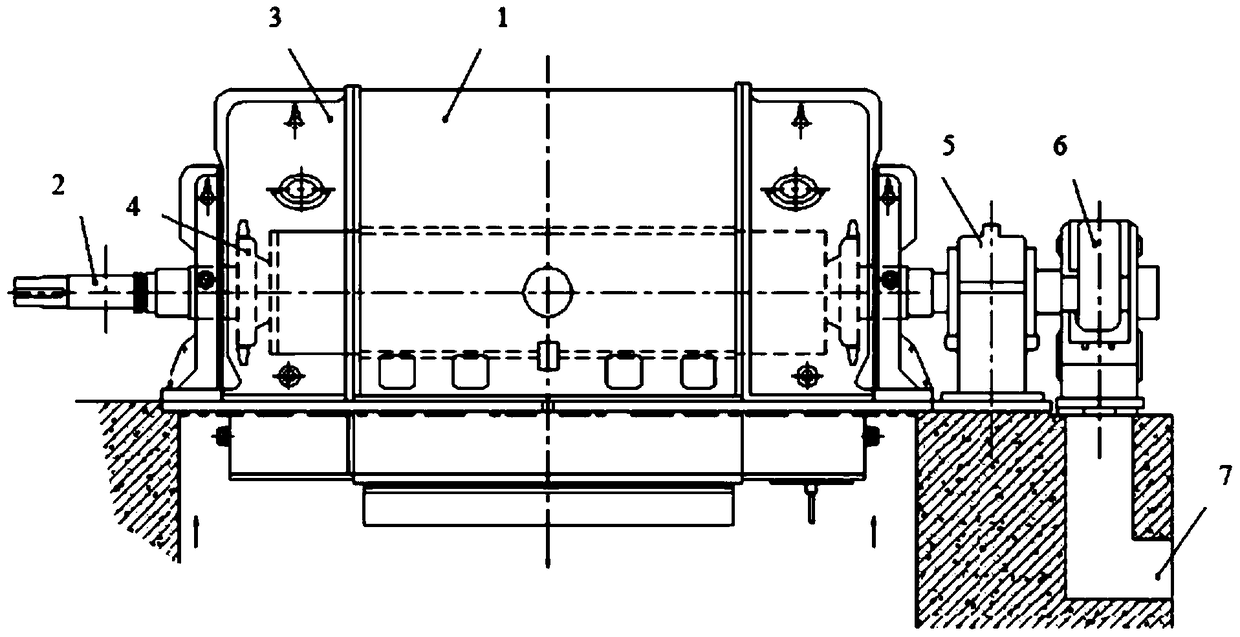
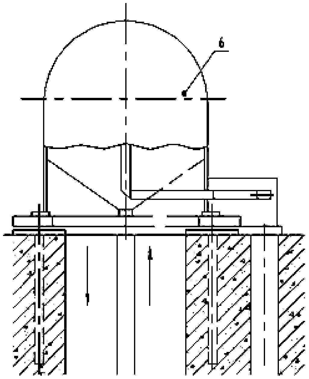
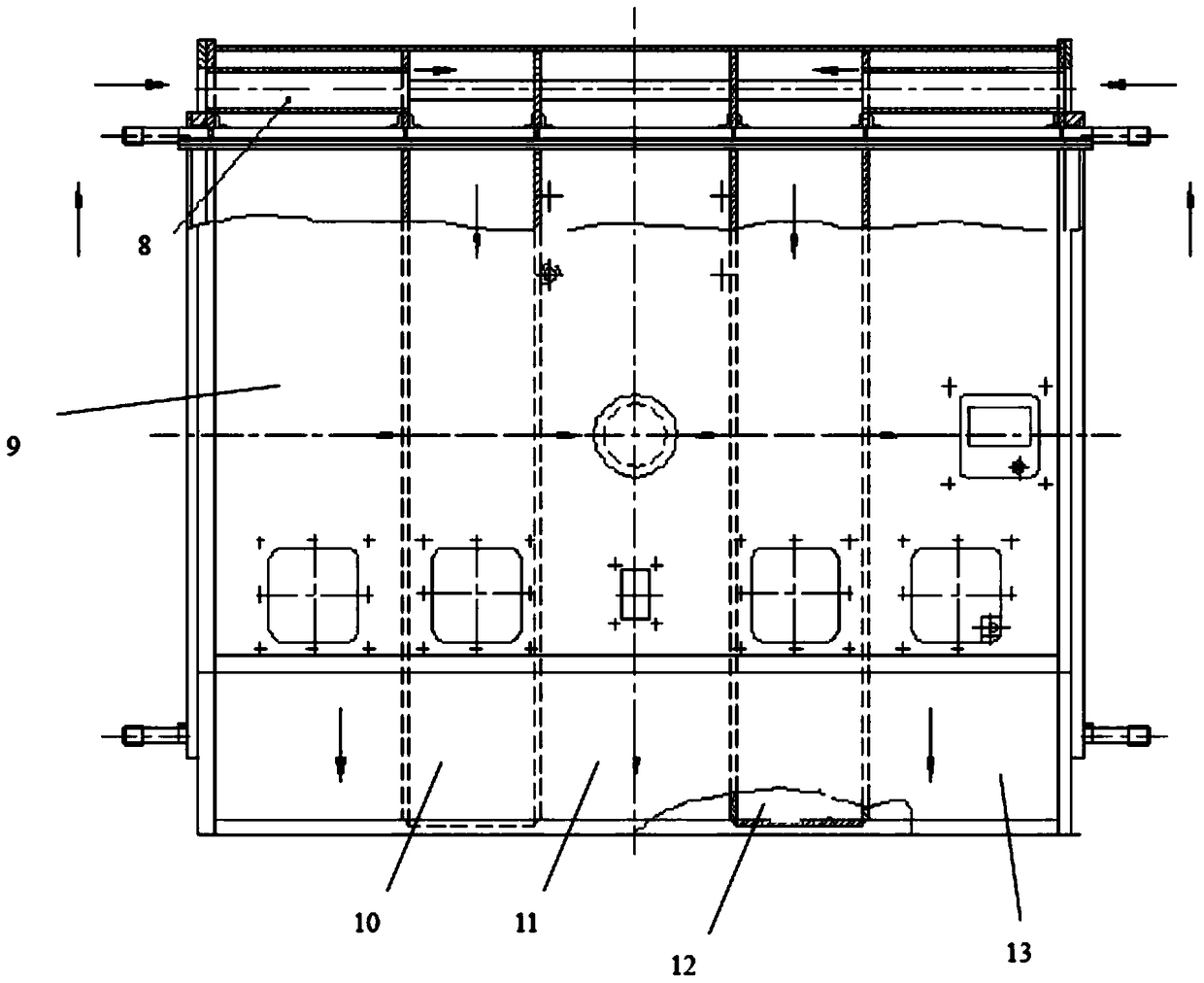
[0023] Such as image 3 and Figure 4 As shown, an air-cooled turbogenerator air path structure includes a stator frame air path, a rotor air path, a cold wind area and a hot air area arranged at the lower end of the stator frame, and a brush air path 7; the stator frame air path includes The stator ventilation pipe 8 located on the upper part of the stator frame 1, and the group of radial air passages distributed vertically and symmetrically inside the stator frame 1 with the center of the stator frame 1 as the center of symmetry, each radial air passage group of the radial air passage group The air ducts communicate with each other, the radial air duct group communicates with the stator ventilation pipe 8, the lower end of the radial air duct group communicates with the hot air area, and the left and right sides of the stator air duct 8 communicate with the cold air area;

[0024] The rotor air path includes an axial air duct, an air gap between the stator and rotor, and a ...


PUM


Abstract

The invention relates to a wind path structure of an air-cooling steam turbine generator. The wind path structure comprises a stator base wind path, a rotor wind path, a cold air area and a hot air area arranged under a stator base, and an electric brush wind path. The stator base wind path comprises a stator ventilation pipe arranged on the stator base and a radial ventilating duct group in symmetrical and vertical distribution in the stator base with the center of the stator base being a symcenter. The rotor wind path comprises an axial air duct, a gap between a stator and a rotor, and a first axial-flow type fan and a second axial-flow type fan which are arranged at the two ends of the rotor respectively, wherein the axial air duct is communicated with the gap between the stator and the rotor; and the rotor wind path is communicated with the stator base wind path. The wind path structure divides the air flow into multiple strands to allow cold air to be contacted with all heating parts of a generator as much as possible; the stator end portion and rotor end portion, which have higher temperature rise, of the generator are cooled preferentially, and then, the generator body portion is cooled; and therefore, each part of the generator can be cooled uniformly.

Description

technical field [0001] The invention specifically relates to an air passage structure of an air-cooled turbogenerator. Background technique [0002] With the continuous increase of the capacity of QF turbogenerators above 30MW, the stator and rotor are more slender and the heat is not easy to dissipate. Due to the need for ventilation and cooling, the temperature rise of the rotor in the electromagnetic calculation exceeds the standard, which requires an air path structure to reduce the temperature rise of the rotor. The brushes and collector rings of the original QF turbogenerator are directly exposed in the air. The disadvantages are that the generator operating environment is noisy, which affects the operator and the surrounding environment, and the brush carbon powder generated by friction is scattered around. It pollutes the operating environment and even affects the safe and normal operation of the generator. Contents of the invention [0003] The object of the pre...

Claims


Application Information

Patent Timeline
Patent Type & Authority Patents(China)
IPC IPC(8): H02K5/20H02K1/20H02K1/32H02K9/28
Inventor 董江伟翁祥玲张华伟蔡恒川周平
Owner SHANDONG QILU ELECTRIC MOTOR MFG
Why Eureka
Try Eureka