
Light source module and L-shaped light guide plate

A technology of a light source module and a light guide plate, which is applied in the field of optical devices, can solve the problems of increasing the complexity and difficulty of the display device, increasing the required cost, increasing the cost of the light source module, etc., and achieving the effect of a good light source

Active Publication Date: 2016-10-05
YANGXIN TECH SUZHOU
View PDF13 Cites 3 Cited by
  • Summary
  • Abstract
  • Description
  • Claims
  • Application Information

AI Technical Summary

Problems solved by technology

Based on the above reasons, the light guide plate also requires additional microstructure processing, so the use of thinner light-emitting diodes, light-emitting strip substrates, heat sinks, and the above-mentioned light guide plates that require additional processing will greatly increase the cost of light source module production, and the overall The complexity, difficulty and required cost of making display devices also increase accordingly

Method used


Image

  • Light source module and L-shaped light guide plate
  • Light source module and L-shaped light guide plate
  • Light source module and L-shaped light guide plate

Examples


Embodiment Construction

[0039] The aforementioned and other technical contents, features and effects of the present invention will be clearly presented in the following detailed description of a preferred embodiment with accompanying drawings. The directional terms mentioned in the following embodiments, such as: up, down, left, right, front or back, etc., are only referring to the directions of the drawings. Accordingly, the directional terms are used to illustrate and not to limit the invention.

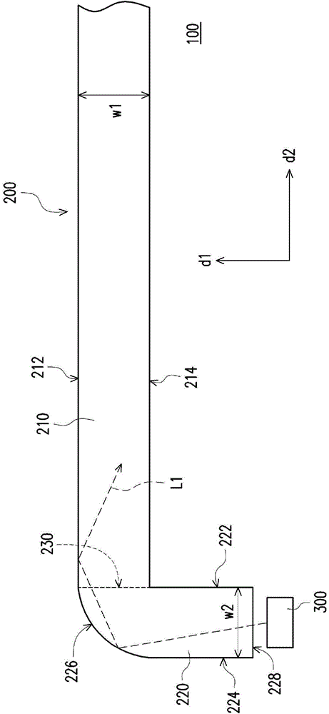
[0040] figure 1 is a partial cross-sectional view of a light source module according to the first embodiment of the present invention. Please refer to figure 1, in the first embodiment of the present invention, the light source module 100 includes an L-shaped light guide plate 200 and a light emitting unit 300 . The L-shaped light guide plate 200 includes a first light guide part 210 and a second light guide part 220 . The first light guide part 210 has a first surface 212 and a second surface 214 , t...


PUM


Abstract

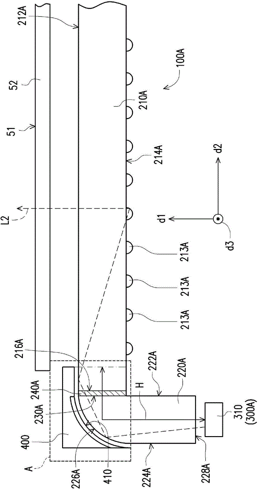
Provided is a light source module. The light source module comprises an L-shaped light guide plate and a lighting unit. The L-shaped light guide plate comprises a first light guide part and a second light guide part. The first light guide part is provided with a first surface and a second surface which are opposite. The second light guide part is provided with a third surface connected to the second surface, a fourth surface opposite to a third surface, a bending surface connected to the first surface and the fourth surface and a light incident surface connected to the third surface and the fourth surface. One end where the third surface and the bending surface close to the first surface is provided with a light emergent section. The light emergent section and the third surface are approximately arranged on the same panel. The light emitting unit is configured besides the light incident surface and emits a light beam towards the light incident surface. The L-shaped light guide plate is also put forward. The L-shaped light guide plate is capable of effectively increasing length of a light mixing region and reducing width of a visual region. The light source module with the L-shaped light guide plate is capable of effectively reducing width of a frame.

Description

technical field [0001] The invention relates to an optical device, and in particular to a light source module with a light guide plate. Background technique [0002] With the evolution of optical technology, the cold cathode fluorescent lamp (cold cathode fluorescent lamp, CCFL) arranged on the side of the light guide plate in the prior art has been replaced by a light-emitting diode (light-emitting diode) with advantages such as long life and low power consumption. , LED) to form a light bar (light bar) to replace, thereby providing a good surface light source for display device applications. At the same time, in the current demand for display devices such as TVs and screens, the design of narrow bezels has become one of the main research and development goals, so the reduction of the mixed light area (non-visible area) of the light guide plate has also become a requirement. One of the important topics for improvement. [0003] In the prior art, when reducing the frame on...

Claims


Application Information

Patent Timeline
Patent Type & Authority Applications(China)
IPC IPC(8): F21V8/00F21V7/10G02B6/00F21Y101/02
Inventor 刘宏威
Owner YANGXIN TECH SUZHOU
Learn More