
Wireless Transmission System of Rotating Electromagnetic Wave Orbital Angular Momentum

A technology of orbital angular momentum and wireless transmission, which is applied in the field of wireless transmission and can solve problems such as difficult reception in airspace

Active Publication Date: 2018-12-11
TSINGHUA UNIV
View PDF3 Cites 0 Cited by
  • Summary
  • Abstract
  • Description
  • Claims
  • Application Information

AI Technical Summary

Problems solved by technology

[0005] The present invention aims to solve at least to a certain extent the problem of difficult reception in space caused by beam divergence in the free space electromagnetic wave orbital angular momentum transmission described in the background

Method used


Image

  • Wireless Transmission System of Rotating Electromagnetic Wave Orbital Angular Momentum
  • Wireless Transmission System of Rotating Electromagnetic Wave Orbital Angular Momentum
  • Wireless Transmission System of Rotating Electromagnetic Wave Orbital Angular Momentum

Examples

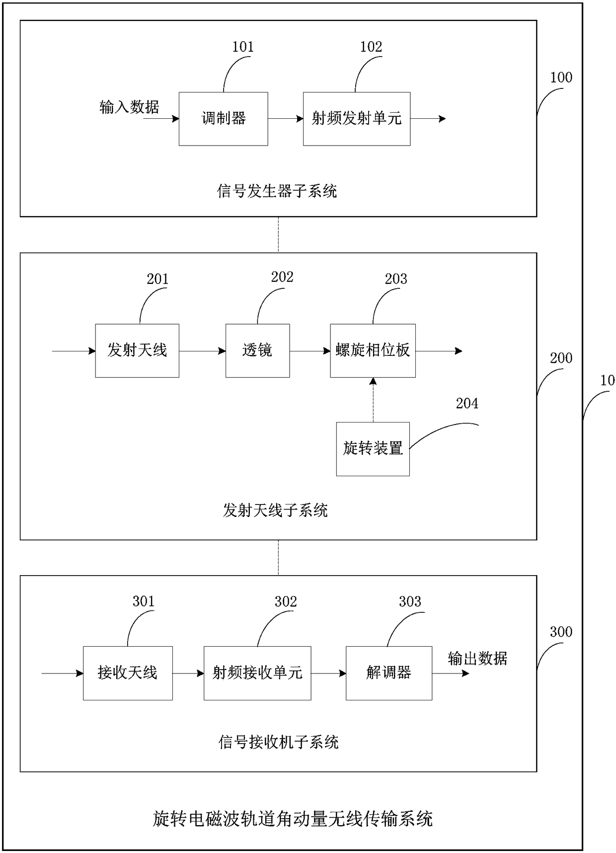

Embodiment Construction

[0025] Embodiments of the present invention are described in detail below, examples of which are shown in the drawings, wherein the same or similar reference numerals designate the same or similar elements or elements having the same or similar functions throughout. The embodiments described below by referring to the figures are exemplary and are intended to explain the present invention and should not be construed as limiting the present invention.

[0026] The following describes the wireless transmission system of rotational electromagnetic wave orbital angular momentum according to the embodiments of the present invention with reference to the accompanying drawings.

[0027] figure 1 It is a structural schematic diagram of a wireless transmission system for rotating electromagnetic wave orbital angular momentum according to an embodiment of the present invention.

[0028] Such as figure 1 As shown, the wireless transmission system 10 includes: a signal generator subsyste...


PUM


Abstract

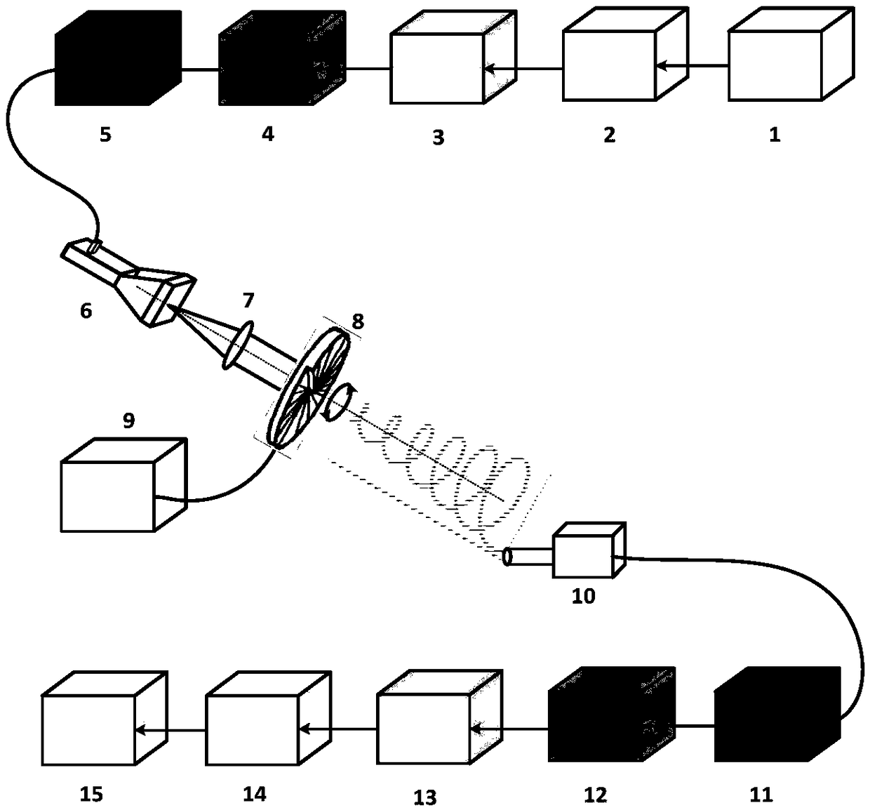
The invention discloses a rotated electromagnetic wave orbital angular momentum wireless transmission system. Different orbital angular momentum state data of transmitting end electromagnetic waves are converted into different frequency offset of receiving end electromagnetic waves through rotating a spiral phase plate, so that orthogonal frequency division multiplexing signals can be formed at a receiving end; and the receiving of orbital angular momentum electromagnetic waves is converted to time-domain orthogonal receiving from space-domain receiving, so that the problem of free spatial divergence caused by an orbital angular momentum electromagnetic wave beam angle in the prior art can be solved, and long-distance, large-capacity and high-spectral efficiency transmission of electromagnetic wave orbital angular momentums can be realized. According to the rotated electromagnetic wave orbital angular momentum wireless transmission system of the invention, baseband signals are modulated and are up-converted to radio-frequency signals, and the radio-frequency signals are fed into a transmitting antenna; after being converged by a lens, the radio-frequency signals are emitted to the spiral phase plate, so that orbital angular momentum electromagnetic waves can be generated; the spiral phase plate rotates under the control of a rotation device, so that rotated orbital angular momentum electromagnetic waves can be generated; after receiving a part of electromagnetic waves, the receiving end carries out down-conversion on the electromagnetic waves and transmits the converted electromagnetic waves to a demodulator; and the electromagnetic waves are demodulated through adopting an orthogonal frequency division multiplexing signal demodulation method.

Description

technical field [0001] The invention relates to the technical field of wireless transmission, in particular to a wireless transmission system for orbital angular momentum of rotating electromagnetic waves. Background technique [0002] Electromagnetic wave orbital angular momentum (OAM) has been widely concerned and deeply researched in academia since it was derived by Allen et al. using Maxwell's equations theory in 1992 and verified by experiments in 1994. The angular momentum of electromagnetic waves includes two parts: spin angular momentum and orbital angular momentum. Spin angular momentum corresponds to the polarization of electromagnetic waves. It has two degrees of freedom, left and right. It has been developed rapidly since it was proposed in the early 1950s. Today's research and products on polarization are very mature. As a new degree of freedom, the orbital angular momentum of the electromagnetic wave advances helically around the propagation axis. [0003] E...

Claims


Application Information

Patent Timeline
Patent Type & Authority Patents(China)
IPC IPC(8): H04L27/26
CPCH04L27/2697
Inventor 张超马路
Owner TSINGHUA UNIV
Learn More