Flow-limiting valve with single door in different direction

A single-door, direction-limited technology, applied in the direction of sliding valves, valve devices, engine components, etc., can solve problems such as external power

Inactive Publication Date: 2016-09-28
戴文平
View PDF6 Cites 0 Cited by
  • Summary
  • Abstract
  • Description
  • Claims
  • Application Information

AI Technical Summary

Problems solved by technology

It is mainly composed of field drainage regulation network, drainage ditches at all levels, waterlogging lakes, drainage sluices, pumping and drainage pumping stations, and drainage capacity and discharge areas. flow, it is necessary to use a flow limiting valve, while the previous flow limiting valves have disadvantages such as needing maintenance and external power.

Method used


Image

  • Flow-limiting valve with single door in different direction
  • Flow-limiting valve with single door in different direction

Examples


Embodiment 1

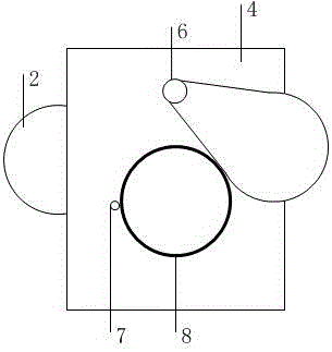
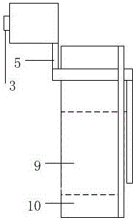
[0010] Such as figure 1 , figure 2 As shown, the present invention includes a pontoon 2, a connecting rod 5, a single door flap 1, a gate 4, a box body 10, a rotating shaft 6, and a sealing rubber ring 8. The gate plate 4 is fixed to the box body 10 On the side, there is a water outlet hole 9 in the middle of the gate, a sealing rubber ring 8 is embedded around the water outlet hole 9 and a limiting column 7 on one side. The rotating shaft is located above the water outlet hole 9, and the pontoon 2 is connected to The rotating shaft 6 is connected, and the rotating shaft 6 is also connected to one end of the single-door water baffle 1, and the single-door water baffle 1 and the pontoon 2 are located on both sides of the box body 10; the pontoon 2 is fixed with a weight adjustment frame 3; the single-door water baffle 1 has a rubber gasket of the same size as the sealing rubber ring 8 on the side facing the water outlet 9, and the single-door water baffle 1 can Seal 80% of the...


PUM


Abstract

The invention discloses a flow-limiting valve with a single door in the different direction. The flow-limiting valve comprises a float bowl, a connecting rod, a single-door water baffle, a gate, a box body, a rotating shaft and a rubber sealing ring. The gate is fixed to one side of the box body. A discharging hole is formed in the middle of the gate. The rubber sealing ring is arranged around the discharging hole. A limiting post is arranged on one side of the valve. The rotating shaft is located above the discharging hole. The float bowl is connected with the rotating shaft through the connecting rod. The rotating shaft is further connected with one end of the single-door water baffle. According to the flow-limiting valve, buoyancy drives the float bowl to move upwards, so that the single-door water baffle is driven to close, and initial rainwater flow limiting is achieved. The flow-limiting valve can be used in municipal water conservancy systems for initial rainwater collection and storm sewage pipeline backflow preventing; no external power and manual maintenance are needed, and the flow-limiting valve is worthy of popularization.

Description

Technical field [0001] The invention relates to the field of drainage devices, in particular to a valve that uses a floating ball to drive a water baffle to limit flow. Background technique [0002] Drainage system refers to the overall combination of drainage collection, transportation, water quality treatment and discharge facilities in a certain way. The general term for all levels of drainage ditch (pipe) and buildings used to remove waterlogging, prevent waterlogging, and prevent salt. It is mainly composed of field drainage adjustment network, drainage ditches at all levels, waterlogging lakes, drainage gates, drainage pumping stations and drainage capacity areas. In rainy days, the rainwater pipe network needs to limit the initial rainwater with more dirt. Flow requires the use of a restrictor valve, while the previous restrictor valve has the disadvantages of requiring maintenance and requiring external power. Summary of the invention [0003] In view of the above-mentio...

Claims


Application Information

Patent Timeline
Patent Type & Authority Applications(China)
IPC IPC(8): F16K3/06
CPCF16K3/06
Inventor 戴文平
Owner 戴文平
Why Eureka
Try Eureka