Double-door different-direction flow-limiting valve

A technology of limit and door stop, applied in the direction of waterway system, sewage discharge, water supply device, etc., can solve the problems of external power and so on

Inactive Publication Date: 2016-09-28
戴文平
View PDF9 Cites 0 Cited by
  • Summary
  • Abstract
  • Description
  • Claims
  • Application Information

AI Technical Summary

Problems solved by technology

It is mainly composed of field drainage regulation network, drainage ditches at all levels, waterlogging lakes, drainage sluices, pumping and drainage pumping stations, and drainage capacity and discharge areas. flow, it is necessary to use a flow limiting valve, while the previous flow limiting valves have disadvantages such as needing maintenance and external power.

Method used


Image

  • Double-door different-direction flow-limiting valve
  • Double-door different-direction flow-limiting valve

Examples


Embodiment 1

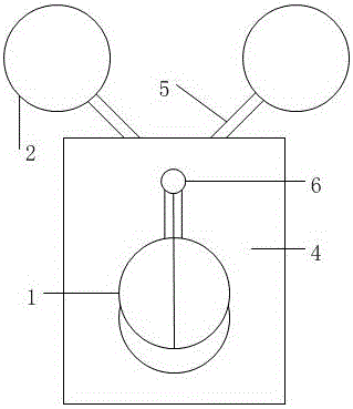
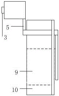
[0009] Such as figure 1 , figure 2 As shown, the present invention includes a buoy 2, a connecting rod 5, a double-door water baffle 1, a gate 4, a box body 10, and a rotating shaft 6. The gate 4 is fixed on one side of the box 10, and the gate There is a water outlet hole 9 in the middle of the plate 4, a sealing rubber ring is embedded around the water outlet hole 9, the rotating shaft 6 is located above the water outlet hole, there are two buoys 2, and the double-door water retaining plate 1 includes two semicircular doors , the two semicircular doors and the two buoys 2 are hinged on the rotating shaft 6, and the double-door fenders 1 and the buoys 2 are located on both sides of the box body 10; the buoys 2 A counterweight adjustment frame 3 is fixed on it; the double-door water retaining plate 1 can close 80% of the cross-section of the water outlet hole 9, and one of the straight sides of the two semicircular doors has a groove, and the other has a protrusion.

[0010...


PUM


Abstract

The invention discloses a double-door different-direction flow-limiting valve which comprises float bowls, connecting rods, a double-door water-blocking plate, a gate plate, a tank, a rotating shaft and a sealing rubber ring. The gate plate is fixed to one side of the tank, a water outlet hole is formed in the middle of the gate plate and is surrounded by the sealing rubber ring, the rotating shaft is located above the water outlet hole, and the float bowls and the double-door water-blocking plate are hinged to the rotating shaft. The double-door different-direction flow-limiting valve utilizes a buoyancy force to drive the float bowls to move upwards so as to close the double-door water-blocking plate, initial rainwater flow limiting is achieved, and the double-door different-direction flow-limiting valve can be used for initial rainwater collection, storm sewage pipeline backward-flowing prevention and other municipal and water-conservancy systems, does not need external power and artificial maintenance and is worthy of popularization.

Description

technical field [0001] The invention relates to the field of drainage devices, in particular to a valve that uses a floating ball to drive a water baffle to realize flow limitation. Background technique [0002] Drainage system refers to the overall combination of drainage collection, transportation, water quality treatment and discharge and other facilities in a certain way. The general term for all levels of drainage ditches (pipes) and buildings used for waterlogging, waterlogging, and salt prevention. It is mainly composed of field drainage regulation network, drainage ditches at all levels, waterlogging lakes, drainage sluices, pumping and drainage pumping stations, and drainage capacity and discharge areas. flow, need to use flow limiting valve, but the previous flow limiting valves need maintenance, need external power and other deficiencies. Contents of the invention [0003] The present invention aims at the above-mentioned deficiencies of the prior art and prod...

Claims


Application Information

Patent Timeline
Patent Type & Authority Applications(China)
IPC IPC(8): E03F1/00E03F7/02
CPCE03F1/00E03F7/02
Inventor 戴文平
Owner 戴文平
Why Eureka
Try Eureka