Demolding driving mechanism for casting mold

A driving mechanism and casting mold technology, applied in the direction of manufacturing tools, casting molding equipment, casting molds, etc., can solve problems such as affecting quality, increasing mold maintenance costs and production costs, and jamming of the ejector pin 12.

Active Publication Date: 2016-09-28
FOSHAN NANHAI SUPERBAND MOLD
View PDF5 Cites 1 Cited by
  • Summary
  • Abstract
  • Description
  • Claims
  • Application Information

AI Technical Summary

Problems solved by technology

However, during the demoulding process, due to the uneven force on the ejector pins 12 or the sticky metal solution on the ejector pins 12, the ejector pins 12 are very prone to adverse phenomena such as being stuck, broken and bent. Downtime for repairing seriously delays the production schedule, and also increases the maintenance cost and production cost of the mold
In addition, because the upper mold 1 is provided with an avoidance through hole for avoiding the ejector pin 12, this will cause the casting a to form a front at the position of the avoidance through hole and affect the quality of the casting a. quality; secondly, the ejector pin 12 will easily lead to deformation or fission of the pressed part of the casting a, directly causing the casting a to be scrapped

Method used


Image

  • Demolding driving mechanism for casting mold
  • Demolding driving mechanism for casting mold
  • Demolding driving mechanism for casting mold

Examples


Embodiment Construction

[0053] The structure of the demoulding driving mechanism and the demoulding method applying the technical solution of the present invention will be further described below in conjunction with the accompanying drawings.

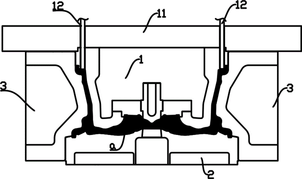
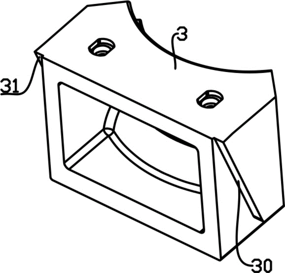
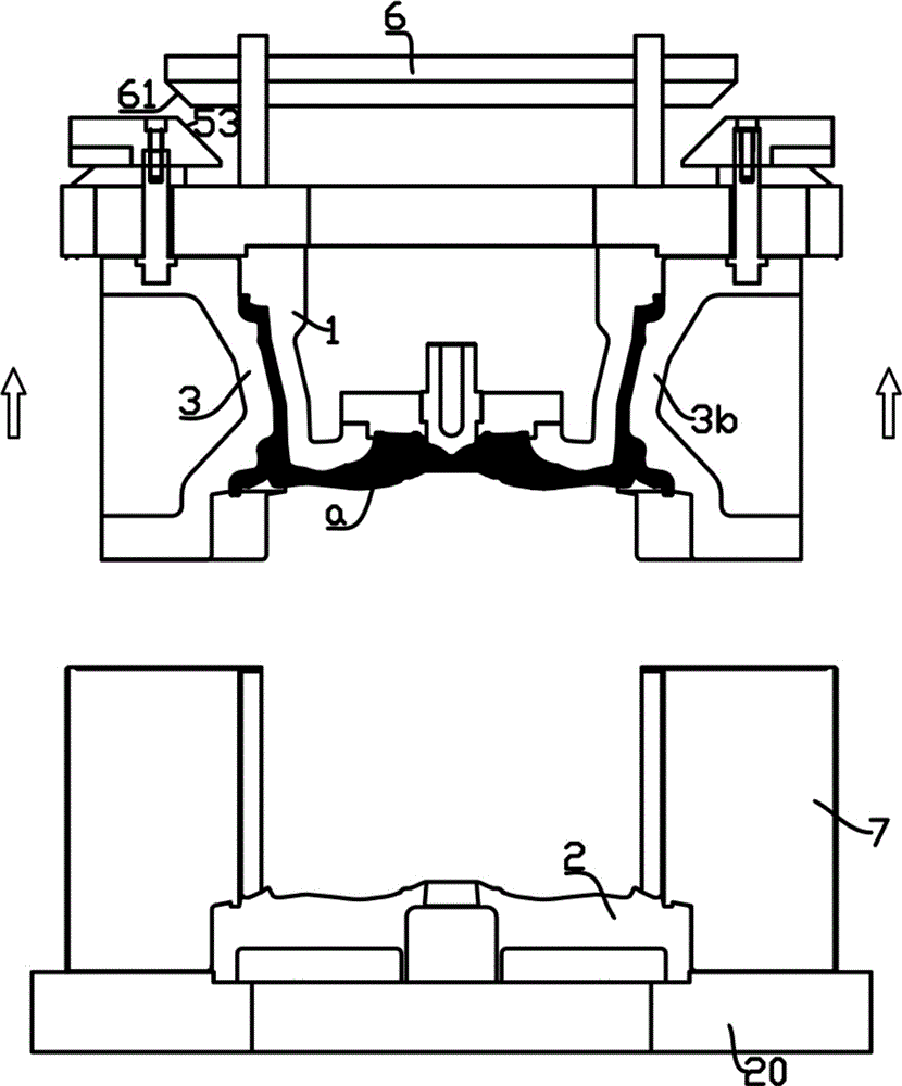
[0054] The demoulding drive mechanism 500 is a part of the casting machine, which mainly plays the role of casting demoulding. The demoulding drive mechanism is combined with the mold to form a two-dimensional demoulding device. Such as Figure 3 to Figure 15 As shown, the mold includes an upper mold 1, a lower mold 2 and a side mold 3 between the upper mold 1 and the lower mold 2, and the side mold 3 includes four sub-side molds (3a, 3b, 3c arranged symmetrically) , 3d), the upper mold 1, the lower mold 2 and the side mold 3 enclose a cavity a for casting a casting 0The demoulding drive mechanism 500 keeps the upper mold 1 and the side mold 3 in a movable connection structure, and also allows the upper mold 1 and the side mold 3 to be preset in the vertical...


PUM


Abstract

The invention relates to a demolding driving mechanism for a casting mold. The demolding driving mechanism comprises an upper mounting plate used for positioning and dragging an upper mold, the upper mounting plate is provided with movable holes which are arranged in a long-hole-shaped mode in the internal direction and the external direction, and sliding blocks are arranged on the upper mounting plate; the demolding driving mechanism further comprises driving rods for connecting side molds, the top end of each driving rod is connected with the corresponding sliding block to form a crank arm assembly, the driving rods penetrate through the upper movable holes to extend downwards to enable the bottom ends of the driving rods to be connected with the side molds, and one crank arm assembly is used in each movable hole in a matched mode; guide portions are arranged on the upper mounting plate, each guide portion is provided with an inclined plane which inclines outwards and upwards, and each sliding block is provided with a sliding plane matched with the corresponding inclined plane and arranged on the inclined plane; the demolding driving mechanism further comprises a pushing plate located on the sliding blocks, and the pushing plate can vertically and perpendicularly push the sliding blocks. In this way, the demolding driving mechanism and the mold are connected into a whole to form a two-dimensional demolding device, and separation among the upper mold, the side molds and a casting is achieved.

Description

technical field [0001] The invention relates to a machine for casting metal castings, in particular to a demoulding driving mechanism for casting molds in the machine for casting metal castings. Background technique [0002] When casting barrel-shaped parts with complex side shapes such as automobile hubs, the casting mold used generally includes upper and lower molds arranged above and below, and side molds arranged on the periphery of the upper and lower molds. Since the casting is relatively large, the mold for casting is very large and heavy, and the pressure required for casting is involved. Generally, the structure of the casting mold for the casting of an automobile hub is relatively complicated, and in order to be able to drive the side mold, upper mold, etc. The movement of the mold or the lower mold completes the opening and closing action of the mold such as the side mold, and a drive cylinder is specially arranged on the left and right spaces of each side mold to...

Claims


Application Information

Patent Timeline
Patent Type & Authority Applications(China)
IPC IPC(8): B22D29/08B22C9/28
CPCB22C9/28B22D17/22B22D17/2236B22D17/263B22D29/08
Inventor 简伟文陈庆勋吴概曾华
Owner FOSHAN NANHAI SUPERBAND MOLD
Why Eureka
Try Eureka