Large-flow ceramic filter element purification equipment

A technology of ceramic filter element and water purification equipment, which is applied in water/sewage treatment equipment, fixed filter element filter, filter separation, etc., and can solve problems such as troublesome operation, loss of ceramic filter element, and loss of filter element

Active Publication Date: 2016-09-28
湖南南山矿泉水有限公司
View PDF6 Cites 8 Cited by
  • Summary
  • Abstract
  • Description
  • Claims
  • Application Information

AI Technical Summary

Problems solved by technology

This operation is cumbersome and easily causes loss to the filter element. The utility model patent CN204798967U improves the above defects: a micro gear reduction motor is used as the power source, and its output shaft is connected to the outer magnetic ring of the magnetic drive mechanism of the ceramic filter element water purifier without disassembly and cleaning. The end or the transmission shaft of the mechanical transmission mechanism is connected; a solenoid valve is connected to the sewage outlet of the water purifier cylinder; the micro gear reduction motor and the sewage solenoid valve are controlled by a time program controller
However, there are still the following problems: 1. A motor is needed as a power source; 2. To remove the dirt that has been cleaned, it needs to be realized by adding a sewage valve; 3. The scrubbing component driven by the motor will continue to scrub the ceramic filter element, which is easy to clean the ceramic filter element. The filter element causes loss and shortens the life of the ceramic filter element

Method used


Image

  • Large-flow ceramic filter element purification equipment
  • Large-flow ceramic filter element purification equipment
  • Large-flow ceramic filter element purification equipment

Examples


Embodiment 2

[0065] combine Figure 19 As shown, this embodiment is further improved on the basis of embodiment 1, the upper water inlet interface is connected to the tap water pipe, the non-drinking water interface is connected to the non-drinking water faucet through the pipe a, and the drinking water The interface is connected to the drinking water faucet through the pipe b; a pipe c is also connected between the pipe a and the tap water pipe, and a regulating valve is connected to the pipe c. The regulating valve is a manual regulating valve.

[0066] The non-drinking water faucet has two parallel water supply pipelines through the pipeline c. When the drinking water faucet draws less water, correspondingly, the dirt accumulated on the outer wall of the ceramic filter element is less, and the ceramic filter element does not need to be cleaned frequently. At this time Increase the effective opening of the manual regulating valve so that more water passes through the pipe c, so that the...

Embodiment 3

[0068] combine Figure 20 with Figure 21 As shown, this embodiment is further improved on the basis of Embodiment 1, the water inlet interface is connected to the tap water pipe, the drainage interface is connected to the non-drinking water faucet through the pipeline a, and the water outlet interface is connected through the pipeline b It is connected with a drinking water tap; a pipe c is also connected between the pipe a and the water pipe, and a regulating valve is connected to the pipe c. The regulating valve is an electric regulating valve; a flow sensor is connected to the pipeline b, the flow sensor is connected to the signal input end of the controller, and the electric regulating valve is connected to the output end of the controller; In the unit time, when the flow measured by the flow sensor is greater than the set value, the controller controls the electric control valve to reduce the opening; in the set unit time, when the flow measured by the flow sensor is le...


PUM

PropertyMeasurementUnit
Angleaaaaaaaaaa
Angleaaaaaaaaaa

Abstract

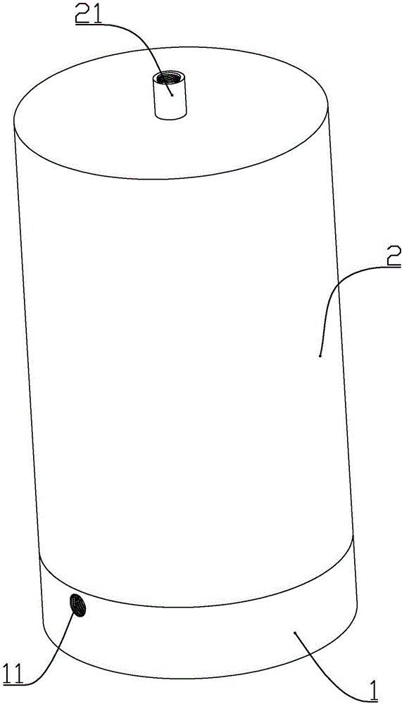
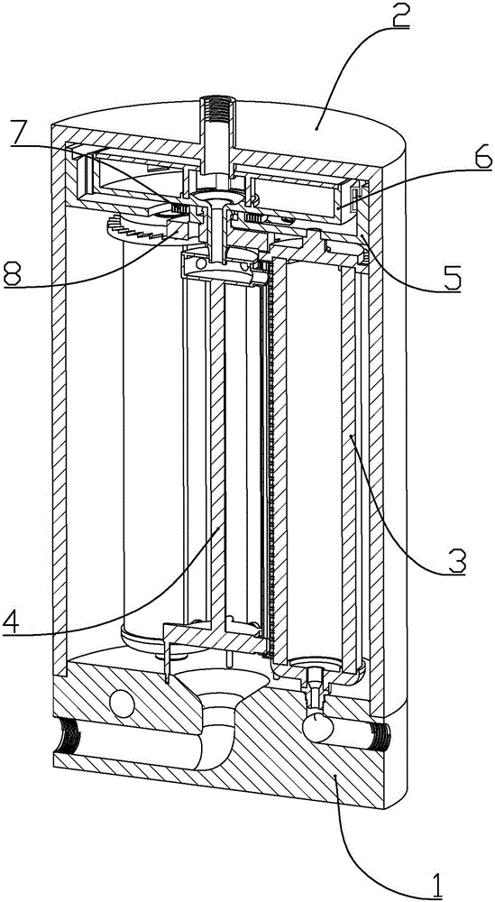
The invention discloses large-flow ceramic filter element purification equipment which comprises a base, a barrel, a plurality of filter element assemblies, brush assemblies, an incomplete gear, an upper positioning frame, a water wheel and a coil spring, wherein the barrel is fixedly connected with the base; the plurality of filter element assemblies are mounted between the barrel and the base; the brush assemblies are mounted among the filter element assemblies; the water wheel is mounted in the upper positioning frame; the coil spring is arranged between the water wheel and the upper positioning frame. Upper faucet pipes sleeve upper water outlets and lower faucet pipes sleeve positioning heads, and thus, water flows into cavities of connecting plates from the upper water outlets and the upper faucet pipes and by utilizing the pressure of the water, end parts of brushing heads on the connecting plates are in contact with ceramic filter elements; the aim of automatically cleaning the ceramic filter elements by power generated by the water pressure is fulfilled; driving latches are only formed at one part of the incomplete gear, and thus, driven clamping latches can only drive the corresponding brush assemblies to rotate clockwise to clean the ceramic filter elements so as to fulfill the aim of not excessively cleaning the ceramic filter elements.

Description

technical field [0001] The invention belongs to the field of water purification equipment, in particular to a large-flow ceramic filter element water purification equipment. Background technique [0002] At present, when the filter element of the ceramic filter element water purifier is cleaned, the water purifier is disassembled, and the dirt cleaned by scrapers or brushes on the ceramic filter element is washed away with clear water to restore the permeability. When the tap water pressure is low or the water quality is poor, it is necessary to remove the water purifier frequently to clean the ceramic filter element. This operation is cumbersome and easily causes loss to the filter element. The utility model patent CN204798967U improves the above defects: a micro gear reduction motor is used as the power source, and its output shaft is connected to the outer magnetic ring of the magnetic drive mechanism of the ceramic filter element water purifier without disassembly and cl...

Claims


Application Information

Patent Timeline
IPC IPC(8): B01D33/073B01D33/37B01D33/46B01D33/48B01D33/72B01D33/80
CPCB01D29/33B01D29/52B01D29/6415B01D29/682B01D29/904B01D33/073B01D33/37B01D33/461B01D33/48B01D33/72B01D33/801C02F1/001C02F2201/009C02F2209/40C02F2303/14
Inventor 胡玥
Owner 湖南南山矿泉水有限公司
Why Eureka
Try Eureka