
Partitioned stator type hybrid excitation motor

A hybrid excitation motor and stator technology, which is applied in the fields of motors and electrical engineering, can solve the problem of the contradiction between the installation space of the excitation winding and the armature winding, and achieve the effect of improving the power density, reducing the influence and the characteristics of high power density.

Active Publication Date: 2016-09-21
JIANGSU UNIV
View PDF8 Cites 18 Cited by
  • Summary
  • Abstract
  • Description
  • Claims
  • Application Information

AI Technical Summary

Problems solved by technology

However, since all excitation sources of the motor are located on the motor stator, it inevitably leads to a contradiction in the installation space between the field winding and the armature winding

Method used


Image

  • Partitioned stator type hybrid excitation motor
  • Partitioned stator type hybrid excitation motor
  • Partitioned stator type hybrid excitation motor

Examples


Embodiment Construction

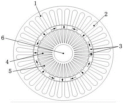
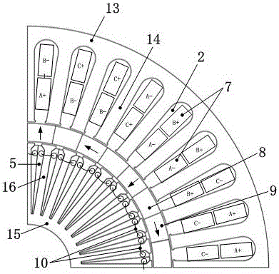
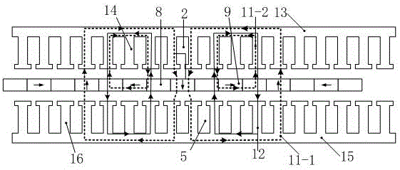
[0019] see figure 1 , The present invention provides a partitioned stator hybrid excitation motor, which includes an outer stator 1 , an intermediate rotor 3 , an inner stator 4 and a rotating shaft 6 in sequence from outside to inside. Outside the rotating shaft 6 is an inner stator 4 , an intermediate rotor 3 and an outer stator 1 coaxially arranged in sequence from the inside to the outside. The intermediate rotor 3 is coaxially installed inside the outer stator 1, and there is an outer air gap between the inner wall of the outer stator 1 and the outer wall of the intermediate rotor 3; the inner stator 4 is coaxially installed inside the intermediate rotor 3, and the inner wall of the intermediate rotor 3 and the outer wall of the inner stator 4 There is also a layer of inner air gap between them. There is a slot in the center of the inner stator 4 for installing the rotating shaft 6 . The intermediate rotor 3 is driven to rotate by the rotating shaft 6 . The thickness o...


PUM


Abstract

The invention discloses a partitioned stator type hybrid excitation motor in the field of electricians and motors. The partitioned stator type hybrid excitation motor is characterized in that the external part of a rotating shaft is provided with an inner stator, a middle rotor and an outer stator which are coaxially arranged in sequence from the inside out, the outer stator is uniformly provided with 36 outer stator teeth along the circumferential direction, and the outer stator teeth are wound with armature windings; the inner stator is uniformly provided with 36 inner stator teeth along the circumferential direction, the inner stator teeth are wound with centralized excitation windings, the middle rotor is forming by uniformly placing 16 magnetic conduction blocks and 16 permanent magnets along the circumferential direction in an alternative manner, the magnetic conduction blocks and the permanent magnets are identical in inner diameter and outer diameter, side surfaces of the magnetic conduction blocks and the permanent magnets are closely fit together, magnetizing directions of adjacent two permanent magnets differ 90 degrees, and the N poles of 16 permanent magnets along the clockwise circumferential direction reversely rotate by 90 degrees anticlockwise in sequence, so that permanent magnet flux at the armature winding side when the permanent magnets carry out excitation independently is effectively increased, and influences imposed on the excitation winding side by a permanent magnetic field are reduced while improving the power density of the motor.

Description

technical field [0001] The invention belongs to the fields of electric engineering and motors, and in particular relates to a structure of a hybrid excitation synchronous motor with two excitation sources of a permanent magnet and an electric excitation winding. Background technique [0002] Compared with traditional electrically excited synchronous motors, permanent magnet motors have the advantages of high power density and high efficiency. However, due to the use of permanent magnet steel for excitation, permanent magnet motors have problems such as difficult adjustment of the air gap magnetic field and limited speed regulation range. The hybrid excitation synchronous motor has two excitation sources: permanent magnet and electric excitation winding. The permanent magnet generates the permanent magnetic field as the main magnetic field of the motor, and works together with the electric excitation field to generate the total air gap magnetic field of the motor. When adjus...

Claims


Application Information

Patent Timeline
Patent Type & Authority Applications(China)
IPC IPC(8): H02K16/04H02K1/14H02K1/27
CPCH02K1/14H02K1/27H02K16/04
Inventor 杜怿汪奇全力朱孝勇肖凤张超丁艳华
Owner JIANGSU UNIV
Learn More