
Sorter

A sorter and body technology, applied in the financial field, can solve the problems of increasing the size of the sorter, easy slack of the rubber ring, low detection efficiency, etc., so as to shorten the detection time, reduce the occupied space and save the internal space.

Active Publication Date: 2016-09-21
SHAOGUAN COLLEGE
View PDF8 Cites 3 Cited by
  • Summary
  • Abstract
  • Description
  • Claims
  • Application Information

AI Technical Summary

Problems solved by technology

[0003] However, the rubber ring of the banknote feeding mechanism tends to loosen after long-term use, which causes the problem of lagging in the transmission of the sorting machine, and even the problem of unsmooth feeding or jamming of banknotes; and the turning processing structure of the banknote feeding channel of the existing sorter is complicated , which increases the volume of the sorting machine and is prone to dust accumulation
In addition, the structure of the banknote dispensing mechanism is complicated, there are many transmission links, the response speed is slow, the manufacturing cost is high, and the accuracy and reliability of the work are not good.
In addition, the existing sorting machine uses a step-by-step detection method, resulting in too long detection time, too many detection channels, and low overall detection efficiency

Method used


Image

  • Sorter
  • Sorter
  • Sorter

Examples


Embodiment Construction

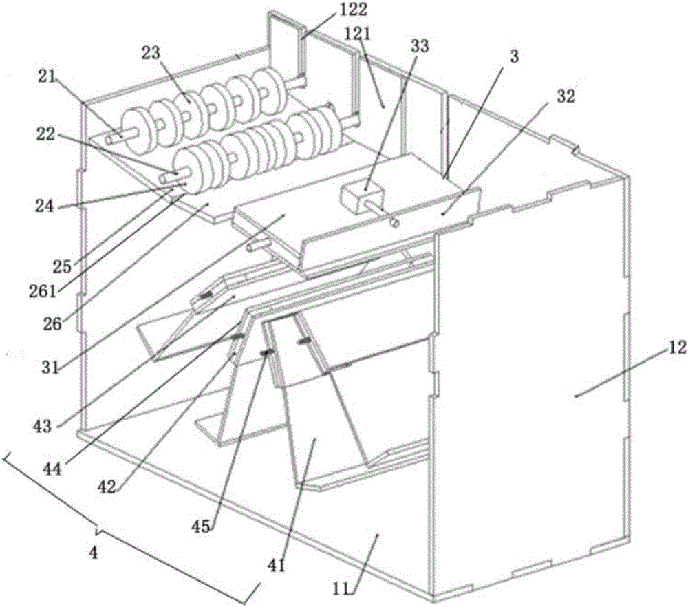
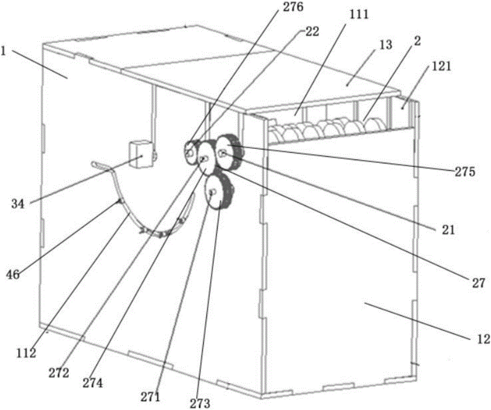
[0018] Please also see figure 1 and figure 2 , figure 1 It is a schematic diagram of the internal structure of the sorting machine in the embodiment of the present invention; figure 2 It is a schematic diagram of the external structure of the sorting machine in the embodiment of the present invention.

[0019] The sorting machine in this embodiment includes a body 1 , a banknote feeding mechanism 2 arranged in the body 1 , a banknote separating mechanism 3 and several banknote receiving mechanisms 4 . The body 1 is provided with a banknote inlet 111; the banknote feeding mechanism 2 is arranged at the banknote inlet 111, and transports the banknotes to be tested into the banknote separating mechanism 3 one by one. The banknote distributing mechanism 3 is connected to the banknote feeding mechanism 2, and identifies and classifies the banknotes to be tested. Several banknote receiving mechanisms 4 are arranged below the banknote separating mechanism 3 at a certain angle t...


PUM


Abstract

The invention discloses a sorter. The sorter comprises a device body; a currency feeding mechanism, a currency separating mechanism, and a plurality of currency receiving mechanisms, which are disposed in the device body. The device body is provided with a currency inlet, and the currency feeding mechanism is disposed on the currency inlet. The currency separating mechanism is connected with the currency feeding mechanism, and the currency receiving mechanisms are disposed on the lower part of the currency separating mechanism. The currency feeding mechanism comprises a currency entwisting wheel shaft, a horizontal wheel shaft, a currency entwisting wheel disposed on the currency entwisting wheel shaft in a sleeved, a horizontal wheel disposed on the horizontal wheel shaft in a sleeved manner, a first currency conveying plate fixedly disposed on the lower part of the currency entwisting wheel, a second conveying currency plate fixedly disposed on the lower part of the horizontal wheel, and a driving mechanism used for driving the currency entwisting wheel shaft and the horizontal wheel shaft to rotate in the same direction. The currency entwisting wheel shaft and the horizontal wheel shaft are horizontally fixedly disposed in the device body. The second currency conveying plate is connected with the first currency conveying plate, and the second currency conveying plate, the first currency conveying plate, and the horizontal wheel are used to form a currency conveying channel. The sorter is advantageous in that by adopting the currency conveying way of combining the currency entwisting wheel and the horizontal wheel, the currency conveying distance is shortened, and the currency blocking failure rate is reduced; by adopting the gear transmission way, the structure is simplified, and the occupied space is reduced.

Description

technical field [0001] The invention relates to the financial field, in particular to a sorting machine. Background technique [0002] Banknote sorting machine, also known as banknote sorting machine, has the functions of identifying the authenticity of banknotes, counting the currency types of banknotes, counting the number of various banknotes, and identifying old and new banknotes. It is an indispensable machine for the financial system. The traditional sorting machine includes a frame, a banknote feeding mechanism, a detection mechanism, a banknote separating mechanism and a banknote receiving mechanism. The banknote feeding mechanism usually uses a combination of a grooved wheel and a rubber ring structure as a tensioning transmission mechanism, and a structure that cooperates with a pressure wheel device or a belt and a pressure wheel is used as a transmission mechanism to realize the transmission of banknotes. In addition, the banknote separating mechanism is compose...

Claims


Application Information

Patent Timeline
Patent Type & Authority Applications(China)
IPC IPC(8): G07D11/00
CPCG07D11/165
Inventor 刘锋洪远泉梁绮婷陈佳德张嘉怡陈涛伍展乐
Owner SHAOGUAN COLLEGE
Learn More