
Side anchor mouth curved surface element generation design method

A design method and edge anchor lip technology, applied in the directions of calculation, image data processing, special data processing applications, etc., can solve the problems of unable to meet the design requirements of various ship types at the same time, prolonging the design cycle, ignoring the processing difficulty and manufacturing errors, etc. Achieve the effect of shortening the design cycle, accurate design, and broad practical application prospects

Active Publication Date: 2016-09-21
JIANGSU UNIV OF SCI & TECH
View PDF7 Cites 4 Cited by
  • Summary
  • Abstract
  • Description
  • Claims
  • Application Information

AI Technical Summary

Problems solved by technology

[0009] However, the above-mentioned patents simply shape the anchor lip surface from the design process, ignoring the processing difficulty and manufacturing errors in the actual processing process; at the same time, the overall surface design of the anchor lip in the above-mentioned patents needs to be based on the existing section of the anchor lip Such a traditional design concept cannot meet the design requirements of various ship types at the same time, and separates the design and manufacturing links, prolonging the design cycle
There is no public report on the design method of the free-form surface of the anchor lip space, which divides the anchor lip according to the type of contact with the anchor during the movement, combines the two links of design and manufacture, and carries out theoretical analysis and anchor pull test at the same time.

Method used


Image

  • Side anchor mouth curved surface element generation design method
  • Side anchor mouth curved surface element generation design method
  • Side anchor mouth curved surface element generation design method

Examples


Embodiment 1

[0043] The present embodiment takes a certain ship type as an example to further illustrate the method of the present invention:

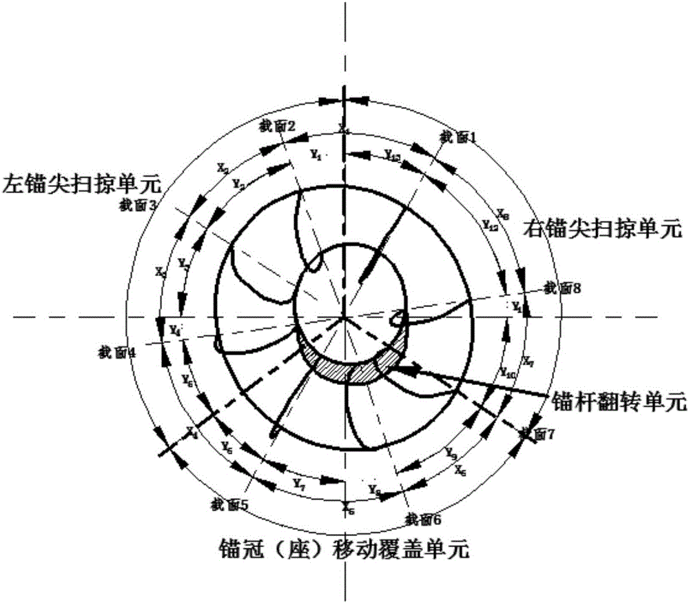
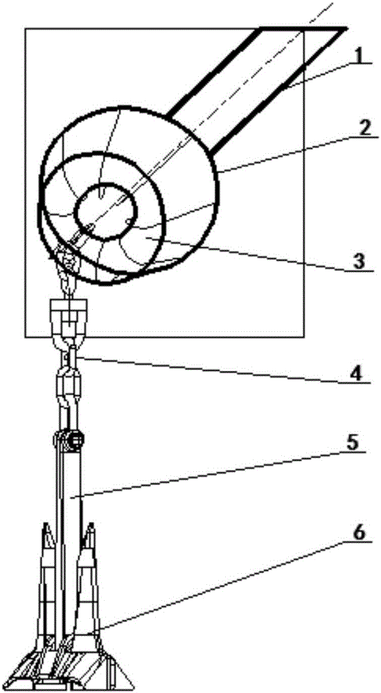
[0044] (1) According to the contact type between the anchor rod 5, the anchor crown (seat) 6 and the anchor lip 3 during the anchor pulling movement, the anchor lip 3 is divided into four regional units: the left anchor tip sweep area unit, the right anchor tip sweep area unit, and the anchor tip sweep area unit. The sweeping area unit, the 5 flipping area unit of the anchor rod, and the 6 moving coverage area unit of the anchor crown (seat), specifically include the following steps:

[0045](1.1) According to different ship types, the anchor lip 3 is firstly divided into sections, and they are respectively divided into the first section to the eighth section according to the counterclockwise rotation direction. The relative arrangement positions of the eight sections on the anchor lip 3 are controlled by angles: the first Angle X between the secti...


PUM


Abstract

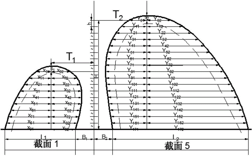
The invention discloses a side anchor mouth curved surface element generation design method. The method comprises the steps of: according to the contact type of an anchor rod, an anchor crown and an anchor mouth surface, dividing an anchor mouth into four units: a left anchor tip sweep unit, a right anchor tip sweep unit, an anchor rod turnover unit and an anchor crown mobile cover unit; by reference to the geometric profile of the anchor rod and the anchor crown, making a generation processing formed cutter according to a proportion of 1:1; anchor pulling and releasing actions are carried out repeatedly, utilizing the formed cutter to perform rough blank generation processing to form an anchor mouth curved surface shape preliminarily; changing different anchor weighing states to generate different types of cutting paths so as to complete smoothing design of the anchor mouth curved surface; and representing the shape of each section of the anchor mouth by means of contour line anchor mouth section profile definition method. The method provided by the invention can realize anchor mouth section profile design and anchor pulling reliability test verification simultaneously, integrates design and manufacturing links, and realizes simultaneous design and manufacturing of anchor mouths meeting a variety of ship types.

Description

technical field [0001] The invention relates to ship anchor lip technology, in particular to a method for generating side anchor lip curved surface elements. Background technique [0002] As an integral part of mooring parts, the design of the anchor lip plays a vital role in the safety of the ship. The anchor lip is designed through traditional wood and steel mold tests, which is costly, long-term, and difficult to modify; designing only with the experience of the master worker cannot guarantee the safety and reliability of the design, especially when encountering unbalanced anchor lips. It is impossible to predict the bad phenomena such as stuck anchor, incomplete fitting, anchor crown (seat) (6) touching the hull plate and so on in the process of pulling the anchor. Since the surface of the anchor lip is a free surface in space, the anchor chain, the anchor rod (5), the anchor crown (seat) (6) and the anchor lip are in the form of multi-rigid body contact and collision d...

Claims


Application Information

Patent Timeline
Patent Type & Authority Applications(China)
IPC IPC(8): G06F17/50G06T17/20
CPCG06F30/15G06T17/20
Inventor 刘志强纪飞飞奚浩孙琦钱兴达
Owner JIANGSU UNIV OF SCI & TECH
Learn More