
Sanitary insert unit

A sanitation embedding and inflow side technology, which is applied to indoor sanitation plumbing installations, water supply installations, buildings, etc., can solve the problems of color distinction interference, manufacturing cost, etc.

Inactive Publication Date: 2016-09-21
NEOPERL
View PDF6 Cites 2 Cited by
  • Summary
  • Abstract
  • Description
  • Claims
  • Application Information

AI Technical Summary

Problems solved by technology

These previously known insert units with their jet regulators, jet regulator housings, jet splitters located in the jet regulator housings and aeration openings arranged in the housing peripheral walls of the jet regulator housings lead to a certain Installation length which necessitates a correspondingly long outflow connection
Since the spout connection part is usually produced in the exterior decoration of the water tap and because the color difference between the water tap and the spout connection part produced separately therefrom is perceived as interfering, such an insert unit and the associated spout connection part Manufacturing is associated with significant manufacturing overhead

Method used


Image

  • Sanitary insert unit
  • Sanitary insert unit
  • Sanitary insert unit

Examples


Embodiment Construction

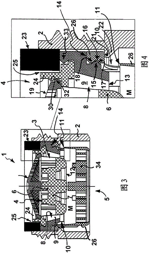
[0024] exist figure 1 and 2 And 3 to 6 show two different embodiments of the sanitary insertion unit 1 . The sanitary insertion unit 1 can be inserted into a sleeve-shaped spout 2 , which can be fitted on a water outlet of a water tap, not further shown here. The sanitary insert unit 1 has a jet regulator 3 , which is designed here as an air-filled jet regulator. The jet regulator 3 has a jet regulator housing whose inflow-side housing end face forms the housing inlet 4 and whose outflow-side housing end face forms the housing outlet 5 . A jet splitter 6 , which is designed here as a cup-shaped diffuser, is arranged in the jet regulator housing. The cup-shaped diffuser has a cup base 7 which serves as an impact surface for deflecting the passing water outwards. The cup-shaped diffuser has in its cup-shaped peripheral wall at least one through-flow opening and preferably a plurality of through-flow openings 8 arranged at equal distances from one another, which open into an ...


PUM


Abstract

A sanitary insert unit (1) is provided having an aerated jet regulator (3) which has a jet regulator housing with a housing inlet (4) and a housing outlet (5), and a jet splitter in the housing interior. One feature of the insert unit is that the jet splitter is configured as an aerated jet splitter and a pot-shaped diffuser which has a pot base (7) serving as an impingement surface for deflecting the flow of water outwards and a pot-shaped circumferential wall having at least one through-flow opening (8) that leads into an annular channel (9). The jet regulator has, in a circumferential wall of its jet regulator housing, at least one aeration channel (10) with an outlet opening leads into the housing interior of the jet regulator housing. The opening edge of the channel outlet opening facing towards the housing outlet is arranged above a cross-sectional plane of the jet regulator housing that extends through the outlet-side front face (12) of the jet splitter.

Description

technical field [0001] The invention relates to a hygienic built-in unit comprising a jet regulator having a jet regulator housing with a housing inlet and a housing outlet, the jet regulator housing in its housing Inside the body there is a jet resolver. Background technique [0002] Various insert units have been created, which can be fitted to the water outlet of a sanitary tap in order to form a uniform, non-splashing and possibly also foaming soft water jet of the water flowing there. For this purpose, these previously known inlay units have a jet regulator with a jet regulator housing, through which the water flowing through can mix with the ambient air in the housing interior. The jet regulator housing of such an air-filled jet regulator has a housing inlet and a housing outlet connected to the clean line cross-section on the water outlet of the sanitary tap, the jet regulator housing in its housing Inside the body there is a jet splitter which can be designed as a ...

Claims


Application Information

Patent Timeline
Patent Type & Authority Applications(China)
IPC IPC(8): E03C1/08E03C1/084
CPCE03C1/08E03C1/084E03C1/00E03C1/086
Inventor G·布卢姆
Owner NEOPERL
Learn More