Needle position structure of crank arm splicer

A patchwork sewing machine and articulating arm technology, which is applied in the direction of cloth pressing mechanism, cloth feeding mechanism, sewing machine components, etc., can solve the problems of insufficient gripping force, poor sewing, dense stitching, etc., and achieve stable feeding, The effect of stable feeding and smooth feeding

Inactive Publication Date: 2016-09-21
ZHEJIANG ZHONGSEN SEWING MACHINE
View PDF10 Cites 1 Cited by
  • Summary
  • Abstract
  • Description
  • Claims
  • Application Information

AI Technical Summary

Problems solved by technology

At present, the needle position of the arm-type roll splicing special machine has insufficient grasping force when passing the splicing joint in practical applications, which makes the speed of the splicing joint slow down and jamming occurs, which leads to poor sewing and needle pitch. densification
In addition, the needle holes on the needle plate are relatively short, which may lead to poor thread take-up effect.

Method used


Image

  • Needle position structure of crank arm splicer
  • Needle position structure of crank arm splicer
  • Needle position structure of crank arm splicer

Examples


Embodiment Construction

[0033] Below in conjunction with the accompanying drawings, the present invention will be further described with specific embodiments:

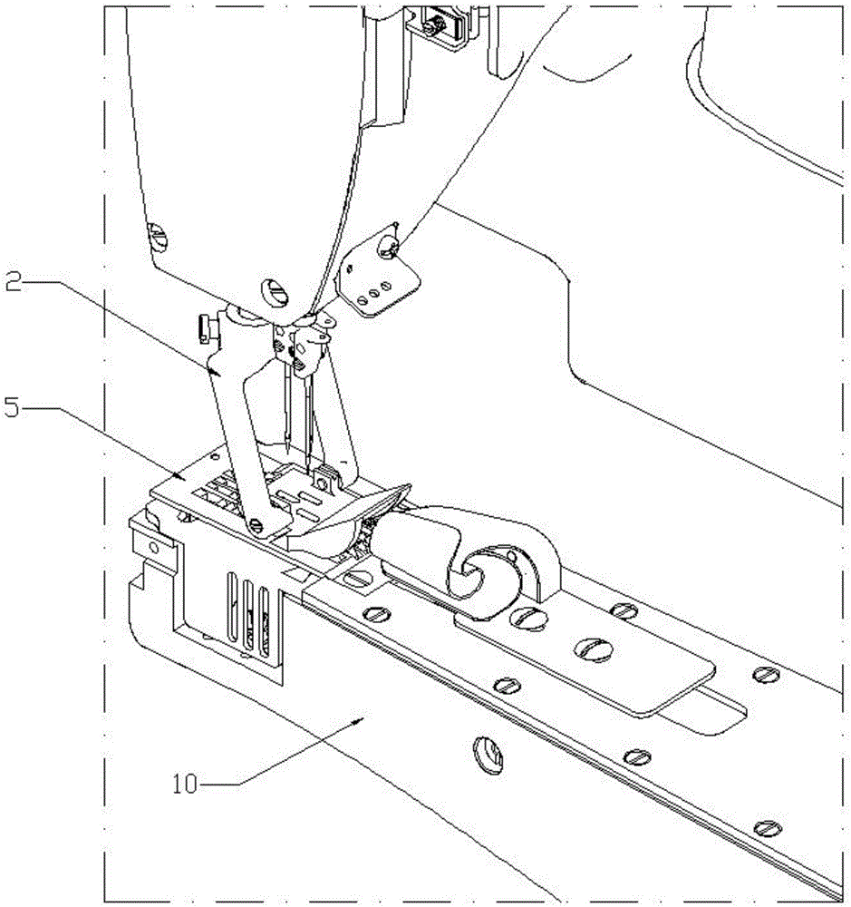
[0034] The up-down, front-rear positional relationship mentioned in the present invention is based on the Figure 7 shall prevail, Figure 7 The top is up, the bottom is down, the left is back, and the right is front.

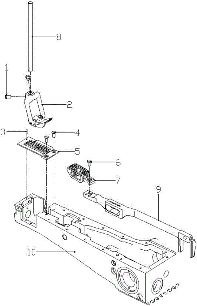
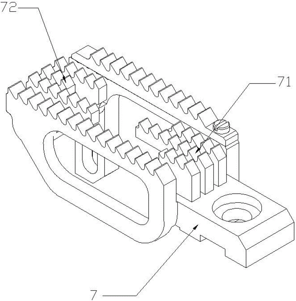
[0035] A needle position structure of a crank arm type sewing machine includes a presser foot rod 8, a presser foot 2, a needle plate 5, a feeding rod 9, and a cloth feeding tooth 7. The presser foot 2 is fixedly connected to the lower end of the presser foot rod 8, The presser foot rod 8 drives the presser foot 2 to reciprocate up and down. The needle plate 5 is fixed on the upper surface of the frame 10 below the presser foot 2. The cloth feeding tooth 7 is fixedly connected to the front end of the feeding rod 9. The cloth feeding tooth 7 The upper surface is provided with several rows of teeth, the needle plate is formed ...


PUM

PropertyMeasurementUnit
Angleaaaaaaaaaa
Widthaaaaaaaaaa
Lengthaaaaaaaaaa

Abstract

The invention belongs to the field of splicer equipment and particularly relates to a needle position structure of a novel crank arm splicer. The needle position structure comprises a pressure foot rod, a pressure foot, a needle plate, a feeding rod and cloth feeding teeth, wherein the pressure foot is fixedly connected with the lower end of the pressure foot rod; the pressure foot rod drives the pressure foot to reciprocate up and down; the needle plate is fixed on the upper surface of a rack below the pressure foot; the cloth feeding teeth are fixedly connected with the front end of the feeding rod; multiple rows of teeth are arranged on the upper surface of the cloth feeding teeth; multiple through slots matched with multiple rows of teeth are formed in the needle plate; multiple rows of teeth extend into corresponding through slots one by one from below the needle plate; the feeding rod drives the cloth feeding teeth to reciprocate back and forth; the pressure foot comprises a support part and a pressure foot plate; the lower end of the support part is articulated with the pressure foot plate; and the front end of the pressure foot plate inclines upward and extends to form a guide part. The needle position structure provided by the invention has the following advantages: the splicing operation is smooth, a process of passing the splicing joint is not blocked, the stitch length does not become smaller, and the stitch take-up effect is relatively good.

Description

technical field [0001] The invention belongs to the field of sewing machine equipment, in particular to a new needle position structure of a crank arm type sewing machine. Background technique [0002] The articulated arm type sewing machine is an elbow-shaped barrel type, which is used for sewing men's clothing, women's clothing, casual clothing, denim clothing, shirts, work clothes, raincoats, etc. At present, the needle position of the arm type seam seam special machine has insufficient gripping force when over-splicing joints in practical applications, which makes the over-splicing joints slower and has jamming phenomenon, which leads to poor sewing and poor stitch length. Densification phenomenon. In addition, the needle hole on the needle plate is short, and the thread take-up effect is not good. SUMMARY OF THE INVENTION [0003] The purpose of the present invention is to provide a needle position structure of a new type of curved arm type sewing machine that provi...

Claims


Application Information

Patent Timeline
IPC IPC(8): D05B29/06D05B35/02D05B73/12
CPCD05B29/06D05B35/02D05B73/12
Inventor 徐志文
Owner ZHEJIANG ZHONGSEN SEWING MACHINE
Why Eureka
Try Eureka