
Weld head

A welding head and spot welding technology, used in welding equipment, resistance welding equipment, manufacturing tools, etc., can solve problems such as mutual collision, damage, and wear of electrodes

Active Publication Date: 2016-09-07
MIYACHI AMERICA
View PDF8 Cites 4 Cited by
  • Summary
  • Abstract
  • Description
  • Claims
  • Application Information

AI Technical Summary

Problems solved by technology

Because the strength of the magnet in the linear actuator motor varies along the stroke of the motor, such conventional horns are susceptible to variations in clamping force that depend on the position of the linear actuator motor
Also, when power is removed from conventional horns, the electrodes tend to strike each other, which can damage or prematurely wear the electrodes

Method used


Image

  • Weld head
  • Weld head
  • Weld head

Examples


Embodiment Construction

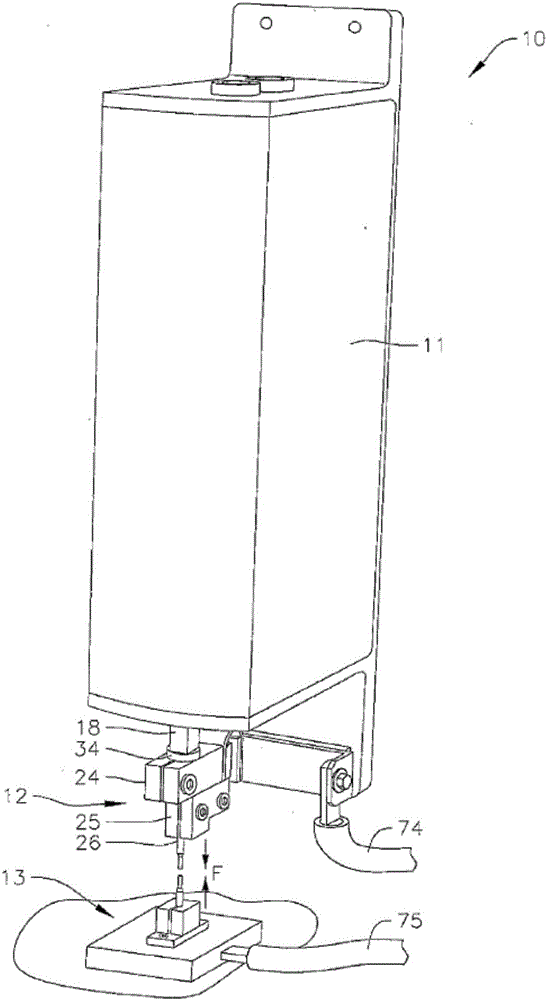
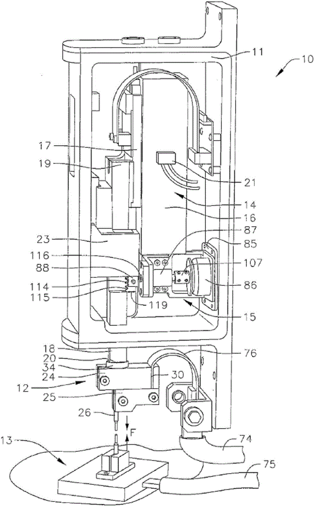
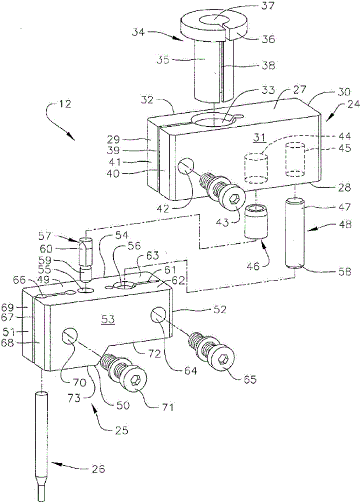
[0012] The present disclosure relates to various embodiments of a horn configured as a pair of opposing electrodes pressed against opposite sides of a component or a pair of side-by-side electrodes pressed against the surface of one or more of the components. Electrodes supply electric current to spot weld two or more parts together. Additionally, embodiments of the horn of the present disclosure are configured to compensate for operating temperature changes or fluctuations within a linear actuation motor configured to push the position of one or both electrodes. Furthermore, embodiments of the horn are configured to compensate for variations in the magnetic field strength of the magnets housed in the linear actuation motor. Embodiments of the horn of the present disclosure also include a detent configured to lock the position of the electrodes when the horn is powered off, thereby preventing the electrodes from striking each other, which could otherwise damage or prematurely ...


PUM


Abstract

A weld head for spot welding two or more components together. The weld head includes first and second electrode assemblies and a linear actuator motor to drive the first electrode assembly into a desired position and apply a desired clamping force. The weld head may include a sensor configured to measure a temperature of the motor and a controller configured to monitor the temperature and adjust the current supplied to the motor to maintain the desired clamping force. The weld head may include linear encoder to measure the position of the linear actuator motor and an algorithm that correlates the position of the motor with a force constant of the motor. Based on the position of the motor and the corresponding force constant of the motor, the controller is configured to adjust the current supplied to the motor to maintain the desired clamping force.

Description

Background technique [0001] Welding heads are typically used to spot weld two or more metal parts, such as two overlapping sheet metal parts, together. The horn typically includes a pair of opposing electrodes arranged to provide pressure to clamp the parts together and to provide electrical current through the parts. Optionally, the horn may include a pair of side-by-side electrodes arranged to provide electrical current through the component. When current is passed through the electrodes, the resistance provided by the parts tends to locally heat the parts around the contact points of the electrodes or at their mating faces, thereby locally melting the metal parts together to form spot welds. [0002] Additionally, conventional horns are configured to support various configurations of electrodes. Different electrode configurations can be selected depending on the desired spot weld size and the structure of the metal parts to be welded. However, removing and replacing elec...

Claims


Application Information

Patent Timeline
IPC IPC(8): B23K11/11B23K11/36
CPCB23K11/115B23K11/311B23K11/315H02P29/60
Inventor D·西林斯基M·罗迪吉耶罗M·A·格林
Owner MIYACHI AMERICA
Learn More