A dynamic measurement system and measurement method for material reflectance changing with temperature

A technology of temperature measurement and dynamic measurement, applied in the field of optics, can solve the problems of difficulty, processing or processing, or not, and achieve the effect of reducing processing costs and improving utilization efficiency.

Active Publication Date: 2018-09-18
INST OF FLUID PHYSICS CHINA ACAD OF ENG PHYSICS
View PDF6 Cites 0 Cited by
  • Summary
  • Abstract
  • Description
  • Claims
  • Application Information

AI Technical Summary

Problems solved by technology

[0004] In the dynamic measurement of material reflectance changing with temperature under laser irradiation by using an integrating sphere reflectometer, the reflectivity of the material surface irradiated by laser is usually measured, and the material surface not irradiated by laser is welded with thermocouples, etc. The temperature measurement method is used to realize the dynamic measurement of the reflectivity of the material changing with the temperature. The curve or data of the material reflectivity changing with the temperature obtained by this measurement method is not the actual spatial position corresponding relationship. Due to the temperature of the material laser irradiation surface Always higher than the non-laser-irradiated surface, so that the temperature variation in the reflectivity versus temperature curve appears to be delayed
In addition, this measurement method requires the material to be in a thin sheet state, and the temperature of the thermocouple measurement point on the surface not irradiated by laser is used to replace the temperature of the reflectance measurement point on the surface irradiated by laser light. However, with the continuous development and progress of material science and technology , it is extremely difficult or impossible to process or process brittle ceramics, polymer materials, etc. in a thin sheet state through traditional mechanical processing, and such materials have the actual situation that thermocouples cannot be welded

Method used


Image

  • A dynamic measurement system and measurement method for material reflectance changing with temperature

Examples


Embodiment

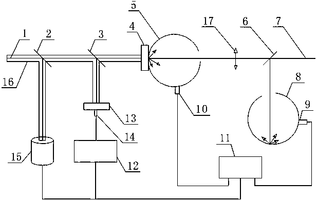
[0020] Such as figure 1 As shown, put two test samples of the same state according to figure 1 The placement shown in , requires that the two test samples have the same linear distance from the 45° 5 / 5 beam splitter 3, and the surface normals of the test samples are perpendicular to each other, so as to achieve the same beam size at the surface position of the two test samples , Laser parameters of the same power density.

[0021] Thermocouples are placed on the non-heated laser beam irradiated surface of the temperature measurement sample for temperature measurement by welding or armoring. The thermocouple installation position is preferably the center point of the non-heated laser beam irradiated surface of the temperature measurement sample, and the metal material is welded. , ceramic or high molecular polymer material for the armor.

[0022]Before the two test samples are heated by the laser beam 1, the probe laser beam 7 is split by the spectroscope, one beam is guided ...


PUM


Abstract

The invention discloses a dynamic measuring system for material reflectivity changing with temperature and a measuring method. The dynamic measuring system comprises measuring samples, light splitters, reflected light intensity change testing systems and temperature data testing systems. The measuring samples are respectively connected with the corresponding reflected light intensity change testing systems or the temperature data testing systems, and photoelectric conversion triggers are arranged among the reflected light intensity change testing systems and the temperature data testing systems and respectively connected with data acquisition recording devices and the temperature data testing systems. The system has the advantages that in a laser irradiation process, corresponding relations of spatial positions of metal materials, ceramics and high-molecular polymer materials are more accurate, curves of the material reflectivity changing with the temperature can be acquired, laser irradiation heat effects of the materials are analyzed and evaluated, laser parameters are optimized in the process of laser cutting, laser cleaning and the like, laser energy use efficiency is improved, machining cost is reduced and the like.

Description

technical field [0001] The invention belongs to a measurement system in the field of optics, and in particular relates to a dynamic measurement system and a measurement method for material reflectance changing with temperature. Background technique [0002] The interaction between the laser and the material starts from the reflection and absorption of the incident laser energy by the material. The initial reflection characteristics of the material to the laser are related to the laser working system (continuous, pulse, repetition frequency, etc.), laser wavelength, and material type and surface. Conditions, radiation environment and other factors. During laser processing, surface cleaning, etc., materials that absorb laser energy through various coupling mechanisms will produce thermal, mechanical, and chemical responses. These physical, chemical, and other responses of materials lead to changes in their surface properties, which will in turn affect The reflective propertie...

Claims


Application Information

Patent Timeline
Patent Type & Authority Patents(China)
IPC IPC(8): G01N21/47G01N21/01
CPCG01N21/01G01N21/4738G01N2021/4735
Inventor 张永强谭福利张黎贺佳唐小松陶彦辉匡学武李建明
Owner INST OF FLUID PHYSICS CHINA ACAD OF ENG PHYSICS
Why Eureka
Try Eureka