Drilling machine used for electric power construction

A technology of electric power construction and drilling rigs, which is applied in the direction of drill pipes, drill pipes, drilling equipment, etc., can solve the problems of low efficiency, low work efficiency, and large consumption of human and financial resources, and achieve the effect of convenient use and high operating efficiency

Inactive Publication Date: 2016-09-07
ZOUPING POWER SUPPLY CO
View PDF6 Cites 6 Cited by
  • Summary
  • Abstract
  • Description
  • Claims
  • Application Information

AI Technical Summary

Problems solved by technology

During the construction of power lines, a large number of electric concrete poles need to be erected. At present, most of the concrete poles are erected by manual excavation with a large number of manpower, which consumes a lot of human and financial resources, and the excavation area is large, which affects the surrounding environment.
Or, some power supply institutes have designed simple auxiliary concrete rod digging tools, but there are the following problems: one, the existing auxiliary tools for drilling are difficult to accurately grasp the required strength of the drilling, and there are often problems that need to be reworked and repeated operations; two. 1. The existing auxiliary drilling tools cannot be adjusted according to the work site. When digging a hole, due to the different geology of different work sites, sometimes the soil quality is more, and sometimes contains hard stones, a tool is used to dig a hole. The efficiency is low and the tool is easy to be damaged; 3. The existing auxiliary tools need to be disassembled every time a hole is punched, the operation speed is slow and the work efficiency is low

Method used


Image

  • Drilling machine used for electric power construction

Examples


Embodiment Construction

[0015] The present invention will be further described through the embodiments below in conjunction with the accompanying drawings.

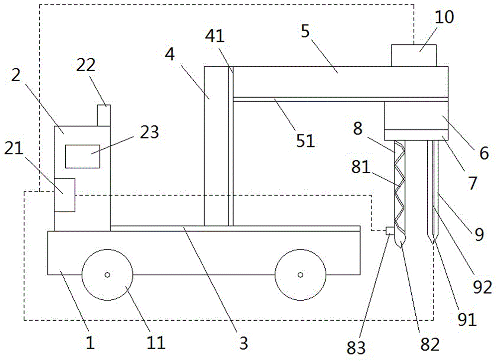
[0016] Such as figure 1 As shown, a drilling rig for electric power construction of the present invention includes a vehicle frame 1, a wheel 11 is installed under the vehicle frame 1, an operation room 2 is installed on the vehicle frame 1, an electric control device 21 is arranged in the operation room 2, and the operation room 2 An observation window 23 is installed on the housing, and an alarm 22 is provided on the top of the operating room 2.

[0017] Vehicle frame 1 upper end surface is provided with track 3 one, and track one 3 is equipped with vertical support 4, and vertical support 4 is provided with track two 41, and track two 41 is equipped with horizontal support 5, and horizontal support 5 is provided with track three 51, and track three 51 is equipped with workbench 6, and workbench 6 is equipped with spindle box 7. Set track 1 ...


PUM


Abstract

The invention relates to a drilling machine used for electric power construction, and belongs to the technical field of construction equipment of a power supply station. The drilling machine comprises a frame installed with wheels. The frame is provided with an operation room. The operation room is internally provided with an electric control unit. An operation room housing is provided with an observation window and an alarm apparatus. The upper end face of the frame is provided with a first track. The first track is provided with a vertical support. The vertical support is provided with a second track. The second track is provided with a horizontal support. The horizontal support is provided with a third track. The third track is provided with a workbench. A spindle cabinet is installed on the workbench. The spindle cabinet is provided with a first drill stem and a second drill stem. The first drill stem is provided with a pressure sensor and a guiding-out groove. The first drill stem is connected with an arc drill bit. The second drill stem is connected with a conical drill bit. The internal of the second drill stem is provided with a dynamometrical bar. The first drill stem and the second drill stem are connected with a motor. The motor, the dynamometrical bar, and the pressure sensor are electrically connected with the electric control unit. The drilling machine can accurately grasp drilling strength, and a proper drill bit is used according to workplaces. The drilling machine is advantaged by convenient drill bit position adjustment and high working efficiency.

Description

technical field [0001] The invention relates to a drilling machine for electric power construction, which belongs to the technical field of construction equipment for power supply stations. Background technique [0002] The power supply belongs to the dispatched agencies of the power company, which are distributed in various towns and towns, and mainly carry out line maintenance services, power outage services, meter reading, and electricity fee collection. When carrying out power line construction operations, a large number of electric concrete poles need to be erected. At present, most of the concrete poles are erected by manual excavation with a large amount of manpower, which consumes a lot of human and financial resources, and the excavation area is large, which affects the surrounding environment. Or, some power supply institutes have designed simple auxiliary concrete rod digging tools, but there are the following problems: one, the existing auxiliary tools for drilli...

Claims


Application Information

Patent Timeline
Patent Type & Authority Applications(China)
IPC IPC(8): E21B7/02E21B15/00E21B17/00E21B17/22E21B44/00
CPCE21B7/02E21B7/022E21B15/003E21B17/00E21B17/22E21B44/00
Inventor 张来顺李峰
Owner ZOUPING POWER SUPPLY CO
Why Eureka
Try Eureka