
A walking-limited concrete road sewer support device

A technology for concrete roads and supporting equipment, which is applied in the field of municipal engineering and can solve problems such as poor equipment stability, poor equipment locking performance, and poor cleaning direction performance

Active Publication Date: 2018-01-09
ZHEJIANG JIRUI CONSTR CO LTD
View PDF4 Cites 0 Cited by
  • Summary
  • Abstract
  • Description
  • Claims
  • Application Information

AI Technical Summary

Problems solved by technology

[0003] In order to solve the above problems, the present invention provides a walking-limited concrete road sewer support device, which can solve the problems of manual operation, high labor intensity, slow cleaning speed, and difficult cleaning in the existing rigid support equipment for sewers. Problems such as low efficiency, poor equipment fixing performance, vibration during equipment cleaning, poor equipment stability, poor cleaning direction performance, poor equipment locking performance, poor equipment lifting adjustment performance and low work efficiency can be realized in the sewer cleaning process. Rigid support function, the equipment is evenly equipped with fixed support points, the equipment has good fixed performance, eliminates the vibration phenomenon in the cleaning process, the equipment has good stability, no manual operation is required, and it has fast cleaning speed, high cleaning efficiency and cleaning direction performance Good, good equipment locking performance, good equipment lifting performance and high work efficiency, providing a new way of rigid support for sewer cleaning

Method used


Image

  • A walking-limited concrete road sewer support device
  • A walking-limited concrete road sewer support device
  • A walking-limited concrete road sewer support device

Examples


Embodiment Construction

[0022] In order to make the technical means, creative features, goals and effects achieved by the present invention easy to understand, the present invention will be further described below in conjunction with specific illustrations.

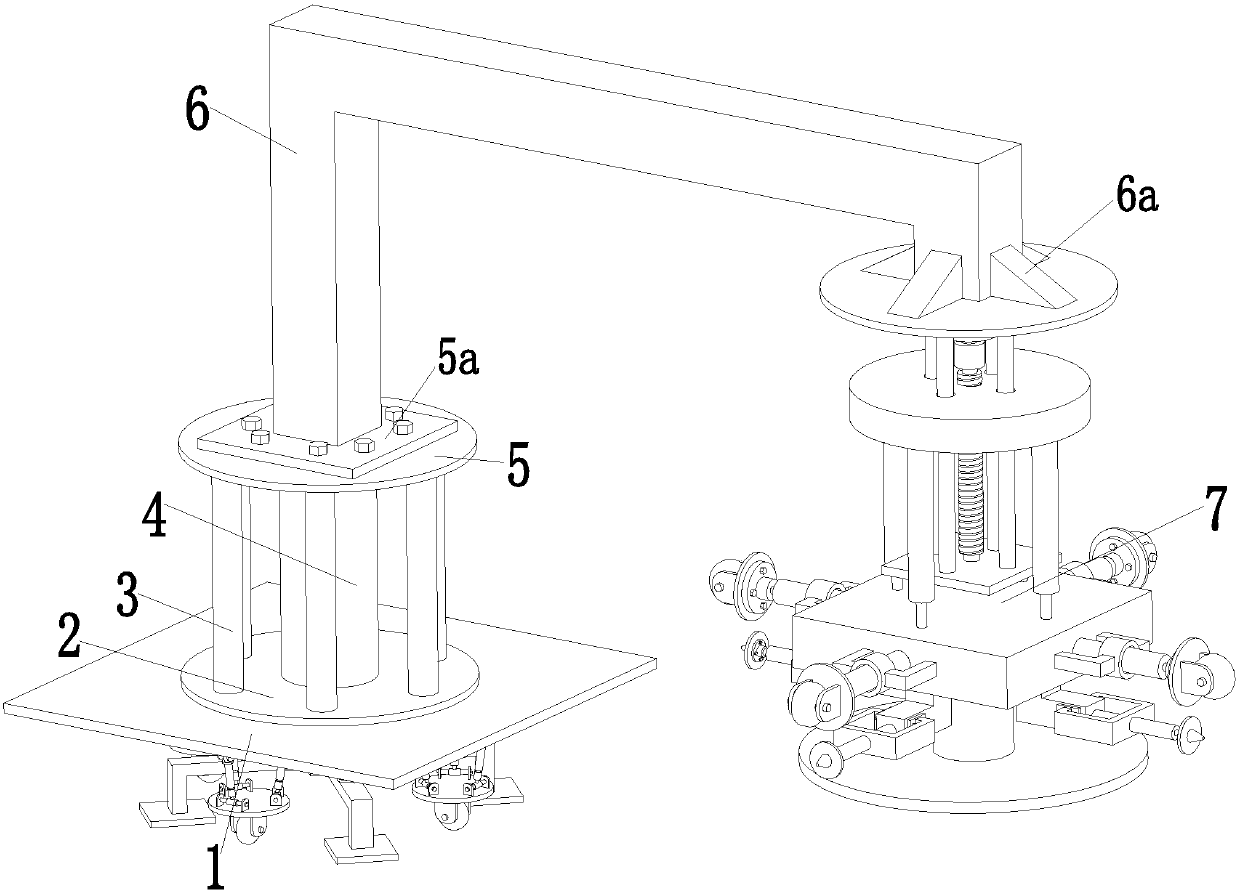
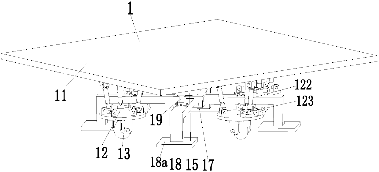
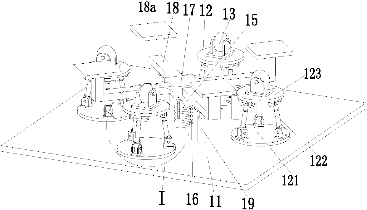
[0023] Such as Figure 1 to Figure 8As shown, a walking limit type concrete road sewer support equipment includes a self-stabilizing walking device 1. The self-stabilizing walking device 1 has good fixing performance and stabilizing performance, and eliminates the shaking phenomenon existing in the cleaning process. The self-stabilizing walking device 1 The middle part of the upper end surface of the walking device 1 is welded with the lower support round platform 2, and the upper end surface of the lower support round platform 2 is uniformly welded with six support columns 3 along the axis direction, and the upper end surface of the lower support round platform 2 is welded with the support column 4, the support column 4 and six support columns. ...


PUM


Abstract

The invention relates to walking-limited concrete road sewer support equipment which comprises a self-stabilization walking device, wherein a lower support circular truncated cone is welded at the middle of the upper end surface of the self-stabilization walking device; six support cylinders are uniformly welded at the upper end surface of the lower support circular truncated cone along the axis direction; support vertical columns are welded at the middle of the upper end surface of the lower support circular truncated cone; an upper support circular truncated cone is welded on the upper end surfaces of the support vertical columns and the six support cylinders; the upper end surface of the upper support circular truncated cone is provided with a connection plate by virtue of a screw; a support bent arm is welded at the middle of the upper end surface of the connecting plate; a lifting locking device is welded at the tail end of the support bent arm; four rib blocks are welded between the periphery of the tail end of the support bent arm and the lifting locking device; the self-stabilization walking device comprises a walking mounting table; the lower end surface of the walking mounting table is symmetrically provided with four support mechanisms connected in parallel. A rigid support function during a sewer clearing process is achieved, and a new way for rigid support for sewer clearing is provided.

Description

technical field [0001] The invention relates to the field of municipal engineering, in particular to a walking-limited concrete road sewer support device. Background technique [0002] Existing highways and urban highways are mainly divided into three types: cement concrete roads, asphalt concrete roads, and recycled asphalt concrete roads. On these highways, there will be a sewer every several hundred meters, so that in heavy rainy days, etc. There will be no water accumulation on the road in bad weather, so as to ensure the smooth driving of the road, but with the long-term use of these sewers, some sundries and sludge will accumulate inside the sewer, and as these sundries and sludge increase, it will Block the sewer. Once the sewer is blocked, the rainwater and sewage will overflow to the road, which will seriously affect the driving of traffic vehicles. Therefore, it is necessary to clean the sewer. The existing sewer sundries and sludge treatment methods mainly use rig...

Claims


Application Information

Patent Timeline
Patent Type & Authority Patents(China)
IPC IPC(8): E03F9/00
CPCE03F9/00E03F9/002
Inventor 陈庆丰杨建威孙仁爱
Owner ZHEJIANG JIRUI CONSTR CO LTD
Learn More