Correction method for tail of strip of continuous rolling unit

A strip and unit technology, applied in the direction of rolling mill control devices, metal rolling, metal rolling, etc., can solve problems such as instability, lag, and poor correction effect

Active Publication Date: 2016-09-07
GUANGXI LIUZHOU YINHAI ALUMINUM IND
View PDF6 Cites 5 Cited by
  • Summary
  • Abstract
  • Description
  • Claims
  • Application Information

AI Technical Summary

Problems solved by technology

[0003] The purpose of the present invention is to provide a method for rectifying the tail of a strip in a continuous rolling mill, which can solve the problem...

Method used


Image

  • Correction method for tail of strip of continuous rolling unit
  • Correction method for tail of strip of continuous rolling unit
  • Correction method for tail of strip of continuous rolling unit

Examples


Embodiment Construction

[0040] The present invention will be described in further detail below in conjunction with accompanying drawing embodiment:

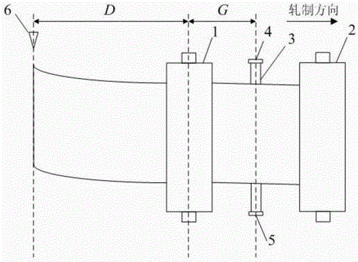
[0041] Such as figure 1 As shown, a metal detector 6 for measuring the tail of the strip is installed before the first stand 1 of the continuous rolling mill, and a first tension measuring roll 3 is installed between the first stand 1 and the second stand 2; A tension measuring roller 3 has a pressure measuring point 4 on the transmission side and a pressure measuring point 5 on the operating side; D is the horizontal distance from the metal detector 6 to the central axis of the roll in the first stand 1, in millimeters; G is the roll gap of each stand The horizontal distance from the pressure measuring point of the tension measuring roller behind it, in millimeters.

[0042] The present invention considers that when the rolling piece of the intermediate billet is rolled to the end of the continuous rolling mill, the metal detector arranged at the entr...


PUM


Abstract

The invention discloses a correction method for the tail of a strip of a continuous rolling unit, and relates to the technical field of metal pressure machining. The method comprises the following steps that a start signal of a strip tail correction program is set, and the strip tail correction program is started when a metal detector arranged at an inlet of the continuous rolling unit detects the tail of an intermediate billet rolled piece; the difference value of roll gaps on the double sides of a second rack of the continuous rolling unit is calculated and corrected; the difference value of roll gaps on the double sides of each of the rest of racks of the continuous rolling unit is calculated and corrected; and self-learning is carried out on the correction factor of the correction value of the difference value of the roll gaps on the double sides of each rack. The correction method solves the problems that in tail lateral bending correction in the existing intermediate billet rolling process, lagging and instability exist, and consequently the correction effect is poor.

Description

technical field [0001] The invention relates to the technical field of metal pressure processing, in particular to a strip tail deflection correcting method for a continuous rolling mill. Background technique [0002] In the production process of hot-rolled coils, the slab ingot is first rolled into an intermediate billet of a certain thickness on a billet rolling mill, and then sent to the continuous rolling unit for one-time rolling into coils. In the process of rolling the intermediate billet, affected by various factors, the intermediate billet will have different degrees of side bending, which is commonly known as camber. When performing continuous rolling, if the side bending of the intermediate billet is not controlled, it will lead to cross-layer defects at the head and tail of the coil. In the current production site, the operator usually corrects the deviation by adjusting the difference between the roll gaps on both sides of the frame after observing the side ben...

Claims


Application Information

Patent Timeline
IPC IPC(8): B21B38/10B21B37/00
CPCB21B37/00B21B38/105
Inventor 许磊刘栩蒋婷李江宇
Owner GUANGXI LIUZHOU YINHAI ALUMINUM IND
Why Eureka
Try Eureka