
Inrush current suppression circuit

A surge current and suppression circuit technology, which is applied in the direction of DC network circuit devices, circuit devices, emergency protection circuit devices for limiting overcurrent/overvoltage, etc., can solve problems such as flow to loads

Inactive Publication Date: 2016-08-31
YAZAKI CORP
View PDF6 Cites 2 Cited by
  • Summary
  • Abstract
  • Description
  • Claims
  • Application Information

AI Technical Summary

Problems solved by technology

[0002] When a device (load) is powered on, an event may occur in which a large current (inrush current) larger than the steady-state current flows from the power source to the load

Method used


Image

  • Inrush current suppression circuit
  • Inrush current suppression circuit
  • Inrush current suppression circuit

Examples


Embodiment Construction

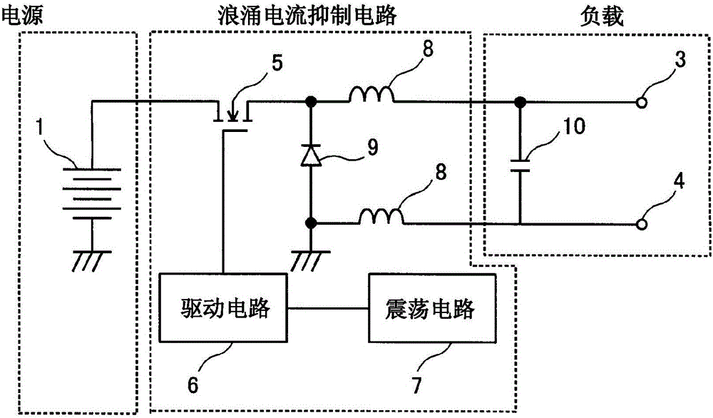
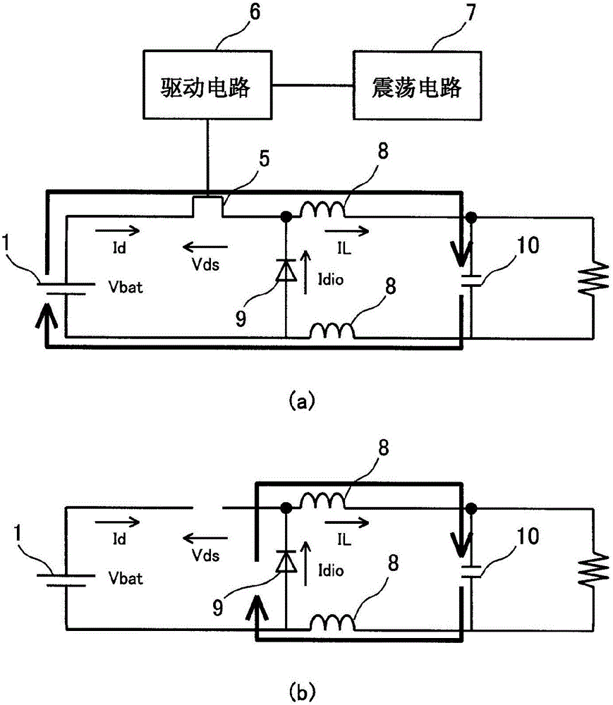
[0032] figure 1 is a circuit diagram showing the configuration of the inrush current suppressing circuit according to the embodiment. The inrush current suppressing circuit according to this embodiment is used to output power to a load that receives an input from the DC power supply 1, and the inrush current suppressing circuit is used to suppress the flow of a surge current from the DC power supply 1 (for example, a battery) to the load. The surge current suppression circuit mainly includes FET 5 , first and second inductors 8 , and freewheeling diode 9 .

[0033] The load includes an input capacitor 10 and a pair of output terminals 3 and 4, and is, for example, an inverter.

[0034] The input capacitor 10 is connected to the DC power supply 1 via a surge current suppressing circuit, and is disposed on the input side of the pair of output terminals 3 and 4 .

[0035] A pair of output terminals 3 and 4 are connected in parallel to the input capacitor 10 , and output an inp...


PUM


Abstract

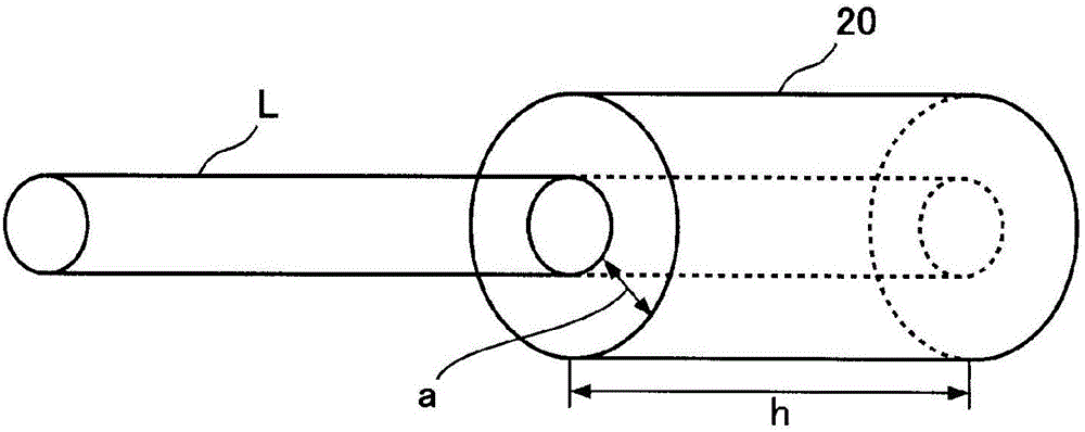
This inrush current suppression circuit suppresses an inrush current flowing to a load, and the load is provided with an input capacitor (10) connected to a power supply (1), and a pair of output terminals (3, 4), which are connected in parallel to the input capacitor (10), and which output a current inputted from the power supply (1). The inrush current suppression circuit is configured from: a FET (5) that is on / off controlled by being connected to the direct current power supply (1); a first inductor (8) connected between a connection point and the FET (5); a reflux diode (9) that connects the cathode to a connection point between the FET (5) and the first inductor (8); and a second inductor connected between the connection point and the anode of the diode. The first and second inductors (8) are configured from a magnetic body covering around an electric wire (L), i.e., a current path.

Description

technical field [0001] The invention relates to a surge current suppression circuit. Background technique [0002] When a device (load) is powered on, an event may occur in which a large current (inrush current) larger than that in a steady state flows from the power source to the load. Inrush current can adversely affect various parts of a device, and inrush current suppression circuits are known for suppressing the flow of inrush current from a power supply. [0003] Patent Document 1 discloses an inrush current suppression circuit utilizing the principle of a step-down chopper circuit. This inrush current suppression circuit has a DC power supply as an input source, and outputs power from a pair of output terminals to a load. The surge current suppression circuit is equipped with a series circuit of FET and coil between the positive pole of the DC power supply and one output terminal. The other output terminal is connected to the ground of the DC power supply, and a fr...

Claims


Application Information

Patent Timeline
Patent Type & Authority Applications(China)
IPC IPC(8): H02H9/02H02J1/00
CPCH02H9/001H02J7/00304H02J1/00H02H9/025
Inventor 松下由宪木村修
Owner YAZAKI CORP
Learn More