Backlight module and liquid crystal display equipment
A technology of backlight module and optical film, applied in optics, nonlinear optics, instruments, etc.
- Summary
- Abstract
- Description
- Claims
- Application Information
AI Technical Summary
Problems solved by technology
Method used
Image

Examples
Embodiment 1
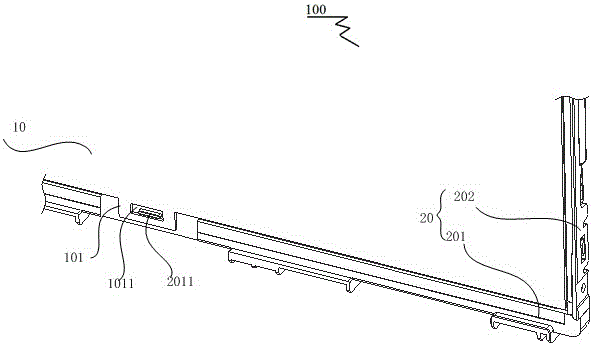
[0032] image 3 It is a schematic diagram of fixing the diaphragm of the backlight module in Embodiment 1 of the present invention; Figure 4 It is a schematic diagram of the A-A section of the backlight module in Embodiment 1 of the present invention; Figure 5 It is a schematic diagram of the C-C section of the backlight module in Embodiment 1 of the present invention; Image 6 It is a B-B cross-sectional schematic view of the backlight module in Embodiment 1 of the present invention. like image 3 , Figure 4 , Figure 5 and Image 6 As shown, Embodiment 1 of the present invention provides a backlight module 200 , including a fixing frame 70 and an optical film set 60 .
[0033] The backlight module 200 in the first embodiment can be applied to a liquid crystal display device. Specifically, the liquid crystal panel is placed on the backlight module 200, and the backlight module 200 and the liquid crystal panel are assembled together by a fixing device to form a liquid...
Embodiment 2
[0046] like Figure 9 As shown, the difference from Embodiment 1 is that the second optical film 603, the first optical film 602, the brightness enhancement film 601 and the fourth optical film 604 sequentially form a staggered layer structure on the protruding part of the edge of the film. . Wherein, the shape and size of the edge protrusion 6011 of the incremental film 601 and the edge protrusion 6031 of the second optical film 603 are the same, and the shape and size of the edge protrusion 6021 of the first optical film 602 and the edge protrusion 6041 of the fourth optical film 604 are the same same size.
[0047] Further, the area of the edge protrusion 6011 of the incremental film 601 is larger than the area of the edge protrusion 6021 of the first optical film 602 .
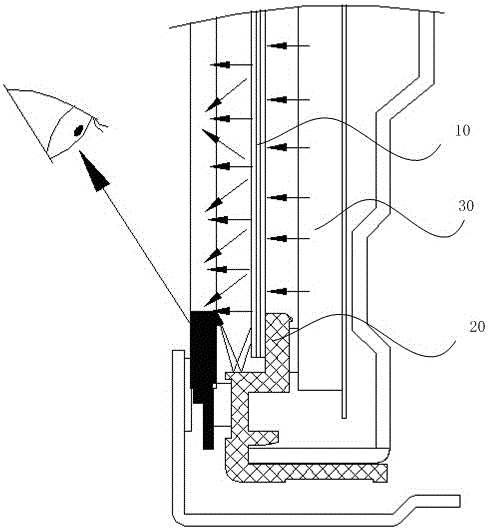
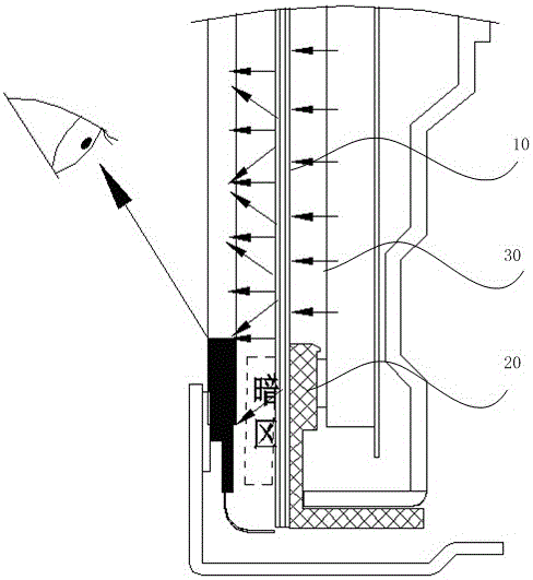
[0048] On the one hand, on the protruding portion of the film that is not covered by the brightness enhancing film 601, the dark area will not be expanded by the brightness enhancing film 601, and th...
Embodiment 3
[0051] like Figure 10 As shown, the same as in the second embodiment, the second optical film 603, the first optical film 602, the brightness enhancement film 601 and the fourth optical film 604 form interlaced staggered layers sequentially on the protruding part of the edge of the film. structure. Wherein, the shape and size of the edge protrusion 6011 of the incremental film 601 and the edge protrusion 6031 of the second optical film 603 are the same, and the shape and size of the edge protrusion 6021 of the first optical film 602 and the edge protrusion 6041 of the fourth optical film 604 are the same same size.
[0052] Different from the second embodiment, the area of the edge protrusion 6011 of the incremental film 601 is smaller than the area of the edge protrusion 6021 of the first optical film 602 .
[0053] On the one hand, on the protruding portion of the film that is not covered by the brightness enhancing film 601, the dark area will not be expanded by the ...
PUM
 Abstract
Description
Claims
Application Information
 - R&D
- Intellectual Property
- Life Sciences
- Materials
- Tech Scout
- Unparalleled Data Quality
- Higher Quality Content
- 60% Fewer Hallucinations
Browse by: Latest US Patents, China's latest patents, Technical Efficacy Thesaurus, Application Domain, Technology Topic, Popular Technical Reports.
© 2025 PatSnap. All rights reserved.Legal|Privacy policy|Modern Slavery Act Transparency Statement|Sitemap|About US| Contact US: help@patsnap.com