
Material temperature control method of sinter-circle-cooling machine

A technology of sintering ring cooler and material temperature, which is applied in the direction of furnace control device, treatment of discharged materials, furnace, etc., which can solve the problems of insufficient utilization of hot waste gas, failure of ring cooling to achieve cooling effect, and reduced production efficiency, etc. , to avoid equipment loss and casualties, improve sinter quality, and reduce production energy consumption

Active Publication Date: 2016-08-31
MCC NORTH (DALIAN) ENG TECH CO LTD
View PDF8 Cites 11 Cited by
  • Summary
  • Abstract
  • Description
  • Claims
  • Application Information

AI Technical Summary

Problems solved by technology

In actual production, due to complex reasons such as fluctuations in the roasting process, unreasonable air volume, and overloaded production, the ring cooling cannot achieve the cooling effect, the hot exhaust gas cannot be fully utilized, and the high temperature of the material may cause fire and burn the equipment. It may even cause major safety accidents such as casualties; it is also possible that the cooling speed is too fast, resulting in a decline in product quality and a reduction in production efficiency.

Method used


Image

  • Material temperature control method of sinter-circle-cooling machine
  • Material temperature control method of sinter-circle-cooling machine
  • Material temperature control method of sinter-circle-cooling machine

Examples


Embodiment Construction

[0031] The present invention will be further described in detail below in conjunction with the accompanying drawings and specific embodiments.

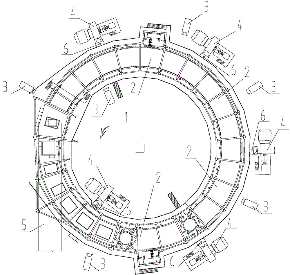
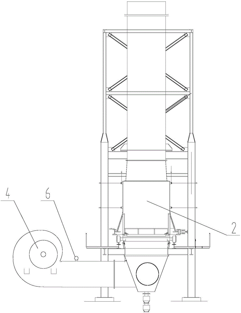
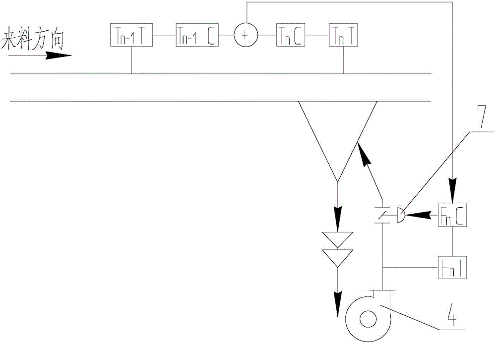
[0032] Such as figure 1 , figure 2 As shown, a method for controlling the material temperature of a sintering ring cooler comprises the following steps:

[0033] Step 1: First, configure a suitable non-contact temperature measuring device 3 according to the measured temperature and the operating conditions of the equipment. The temperature measuring device 3 itself should be resistant to high temperature; then, install a mounting bracket on the side of the ring cooler 1 to install the temperature measuring device 3. The installation height and angle of the temperature measuring device 3 on the mounting bracket should be adjustable, so as to achieve the purpose of keeping the equipment away from the heat source without affecting the measurement; then, through the non-contact Type temperature measuring device 3, which measures the te...


PUM


Abstract

The invention discloses a material temperature control method of a sinter-circle-cooling machine and belongs to the technical field of measurement and control of the metallurgical industry. The material temperature control method includes the steps that the surface temperature values of materials on a trolley of the sinter-circle-cooling machine in all blasting sections in the cooling process are measured by non-contact temperature measurement devices arranged at the blasting sections of the sinter-circle-cooling machine, and the temperature values are transmitted to a central control unit, so that the actual temperature change value of a temperature field of the sinter-circle-cooling machine is obtained; the ventilation quantities of outlets of air blowers in the cooling process are obtained through measurement by flow meters at the outlets of the air blowers, and the ventilation quantities are transmitted to the central control unit, so that the flow change value of the outlets of the air blowers is obtained; according to the technical requirement for the thermal parameters of the sinter-circle-cooling machine, an ideal temperature curve needed in the production progress is set, that is, the initial temperature set value is determined, the deviation between the actual temperature change value of the temperature field of the sinter-circle-cooling machine and the initial temperature set value serves as a system disturbance, the flow change value of the outlets of the air blowers serves as a system feedback, and the ventilation quantities of the air blowers are controlled by controlling the opening degrees of air gates of the air blowers.

Description

technical field [0001] The invention belongs to the technical field of measurement and control in the metallurgical industry, and in particular relates to a material temperature control method for a sintering ring cooler, which is mainly used for continuous automatic indirect monitoring and control of the material temperature in each blast section of the sintering ring cooler. Background technique [0002] The cooling process of the ring cooler is to blow a large amount of fresh cold air from the bottom of the hot ore through the blower to cool the hot ore on the trolley through heat exchange. The hot ore needs to be cooled to a certain temperature on the ring cooler trolley through each cooling section Afterwards, carry out transshipment through belt conveyer 5 again. The usual temperature control method of the annular cooler only pays attention to the temperature of the hot air after cooling and the temperature of the material after cooling through the temperature measurin...

Claims


Application Information

Patent Timeline
Patent Type & Authority Applications(China)
IPC IPC(8): F27D15/02F27D19/00
CPCF27D15/02F27D19/00F27D2019/0003
Inventor 潘龙寿宏飚
Owner MCC NORTH (DALIAN) ENG TECH CO LTD
Learn More