Head structure for generator and assembly method for head structure

A generator and head technology, which is applied in the field of generator head structure and assembly, can solve the problems of unstable combustion, low temperature resistance, and easy burning of nozzles, so as to avoid directly facing the combustion chamber and prevent high temperature burning. Erosion, the effect of reducing operating costs

Active Publication Date: 2016-08-31
CNPC GLOBAL SOLUTIONS LTD +1
View PDF7 Cites 0 Cited by
  • Summary
  • Abstract
  • Description
  • Claims
  • Application Information

AI Technical Summary

Problems solved by technology

[0004] The above-mentioned generator has high combustion temperature, high pressure, and strong high-temperature oxidation property. The generator head structure located below the generator in the prior art is not resistant to high temperature and oxidation; The nozzle inside is also easy to burn, and the effect of mixing pure oxygen and natural gas with the nozzle is not good, which will easily lead to unstable combustion

Method used


Image

  • Head structure for generator and assembly method for head structure
  • Head structure for generator and assembly method for head structure
  • Head structure for generator and assembly method for head structure

Examples


Embodiment approach 1

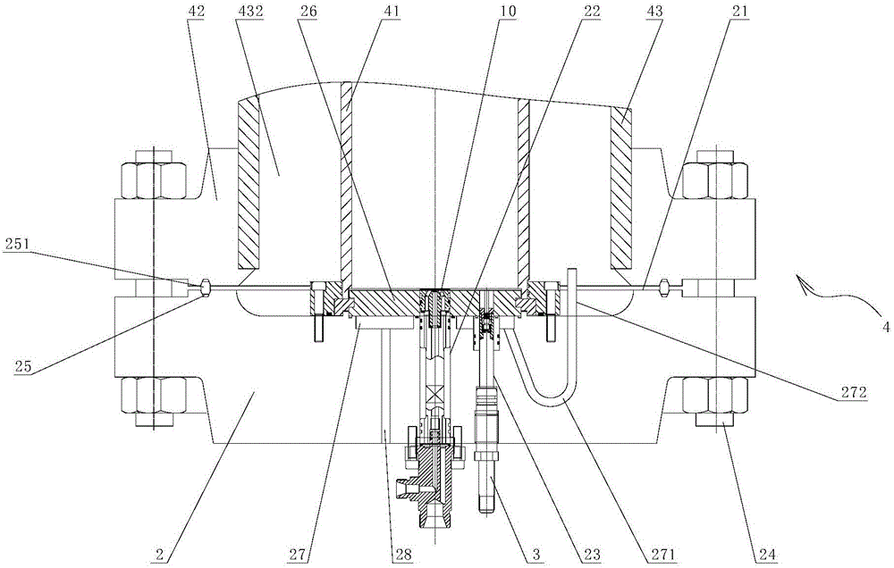
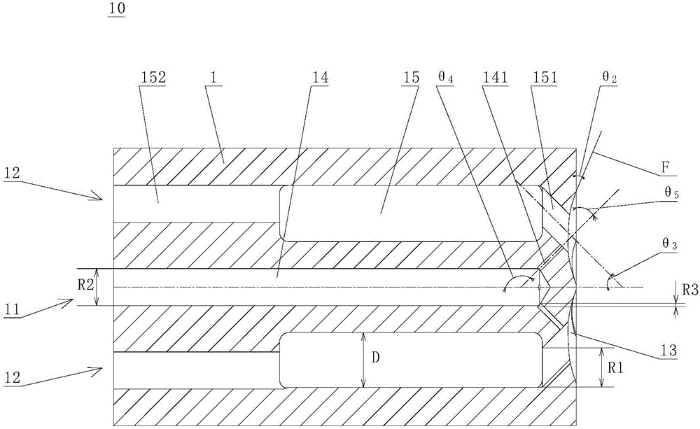
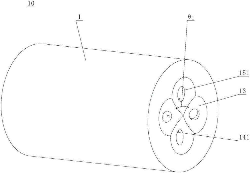
[0040] Such as Figure 1 to Figure 4 As shown, the present invention provides a generator head structure, which includes a head body 2, a combustion nozzle 10 and an ignition electrode 3, wherein: the head body 2 has an inner end surface 21 opposite to the combustion chamber 41 of the generator 4 , the head body 2 is provided with a nozzle channel 22 and an ignition electrode channel 23; the combustion nozzle 10 is located in the nozzle channel 22; the combustion nozzle 10 has a nozzle body 1, and one end of the nozzle body 1 has a fuel inlet 11 and pure oxygen inlet 12, the other end of which is formed with a plurality of diaphragm outer cavities 13, and a plurality of the diaphragm outer cavities 13 are arranged opposite to the combustion chamber 41 of the generator 4; wherein, the nozzle body 1 is provided with A fuel channel 14, one end of the fuel channel 14 communicates with the fuel inlet 11, and the other end of the fuel channel 14 communicates with a plurality of the ...

Embodiment approach 2

[0066] Such as Figure 1 to Figure 4 As shown, the present invention also provides an assembly method of the generator head structure, the assembly method is the generator head structure assembly method of Embodiment 1, the structure, working principle and The beneficial effect is the same as that of the first embodiment, and will not be repeated here. Described assembly method comprises the steps:

[0067] a) The combustion nozzle 10 is installed in the nozzle channel 22 of the head body 2, and the ignition electrode 3 is installed in the ignition electrode channel 23 of the head body 2;

[0068] b) The head body 2 is sealed and installed at the bottom of the combustion chamber 41 of the generator 4 , and the combustion nozzle 10 and the ignition electrode 3 are both arranged opposite to the combustion chamber 41 .

[0069] Specifically, in step a), after the combustion nozzle 10 and the ignition electrode 3 are installed in the head body 2, step b) is carried out, and the ...


PUM


Abstract

The invention provides a head structure for a generator and an assembly method for the head structure. The head structure for the generator comprises a head body, a combustion nozzle and an ignition electrode, wherein a nozzle channel and an ignition electrode channel are formed in the head body; the combustion nozzle is arranged in the nozzle channel and is provided with a nozzle body; a fuel inlet and a pure oxygen inlet are formed in one end of the nozzle body; a plurality of diaphragm outer cavities are formed in the other end of the nozzle body; a fuel channel which communicates with the fuel inlet is formed in the nozzle body; the other end of the fuel channel communicates with the plurality of diaphragm outer cavities through a plurality of fuel inclined holes; the fuel inclined holes are radially formed in an outward inclined manner in the spraying direction of fuel; a pure oxygen channel which communicates with the pure oxygen inlet is also formed in the nozzle body; the other end of the pure oxygen channel communicates with the plurality of diaphragm outer cavities through a plurality of pure oxygen inclined holes; the pure oxygen inclined holes are radially formed in an inward inclined manner in the spraying direction of pure oxygen; and the ignition electrode is arranged in the ignition electrode channel. The head structure for the generator resists high temperature and oxidation, has a safe and reliable structure and is long in service life.

Description

technical field [0001] The present invention relates to a generator head structure and an assembly method thereof, in particular to a generator head structure and an assembly method thereof in the high-pressure combustion technical field. Background technique [0002] Multivariate thermal fluid technology Thermal exploitation of heavy oil is a very efficient new technology, which has the advantages of high combustion efficiency, zero carbon injection, environmental protection and energy saving. Well productivity and enhanced oil recovery. [0003] Multivariate thermal fluid technology is used in oil sand mining, and its core equipment is the generator. At present, the composition of the multivariate thermal fluid output by the generator requires the removal of nitrogen or the reduction of nitrogen content, mainly through the use of pure oxygen with an oxygen content of more than 90% and natural gas Blending way to achieve high pressure and complete combustion needs. [000...

Claims


Application Information

Patent Timeline
Patent Type & Authority Applications(China)
IPC IPC(8): F22B33/00F23D14/32F23D14/78E21B43/243
CPCE21B43/243F22B33/00F23D14/32F23D14/78
Inventor 吴耀文梅立新李国诚陈龙陆峰司军涛朱伟宋宇波梅奕中李兴儒徐梁张建忠
Owner CNPC GLOBAL SOLUTIONS LTD
Why Eureka
Try Eureka