
An exhibition hall with a single luminous body to illuminate the ceiling

A luminous body, a single technology, applied in lighting applications, lighting devices, fixed lighting devices and other directions, can solve the problems of complicated disassembly and assembly of roofs and lamps, low installation and disassembly efficiency, waste of electric energy, etc., to reduce the complexity of wiring, Ease of maintenance and installation, and the effect of reducing potential safety hazards

Active Publication Date: 2018-03-30
NANJING GUOHAO DECORATION INSTALLATION ENG
View PDF4 Cites 0 Cited by
  • Summary
  • Abstract
  • Description
  • Claims
  • Application Information

AI Technical Summary

Problems solved by technology

[0003] The technical problem to be solved by the present invention is: usually a plurality of lighting lamps are installed on the roof structure when illuminating the exhibition hall. In order to improve the effect of lighting decoration, the sunshade is installed on the lighting lamps. Installation makes the disassembly and assembly of the roof and lighting lamps complicated, cumbersome wiring, and waste of electric energy; and each lighting lamp is equipped with a shading cover, which reduces the efficiency of installation and disassembly

Method used


Image

  • An exhibition hall with a single luminous body to illuminate the ceiling
  • An exhibition hall with a single luminous body to illuminate the ceiling
  • An exhibition hall with a single luminous body to illuminate the ceiling

Examples


Embodiment Construction

[0020] The above solution will be further described below in conjunction with specific embodiments. It should be understood that these examples are used to illustrate the present invention rather than to limit the scope of the present invention. The implementation conditions used in the examples can be further adjusted according to the conditions of specific manufacturers, and implementation conditions not specified are usually conditions in routine experiments.

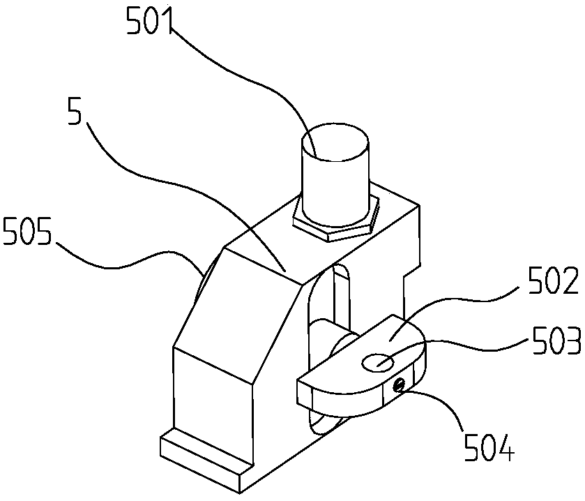
[0021] Such as Figure 1-Figure 4 As shown, figure 1 Is a schematic diagram of a three-dimensional structure provided by an embodiment of the present invention, figure 2 for figure 1 Schematic diagram of partial decomposition structure, image 3 It is a schematic diagram of the structure of the reflector adjusting device provided by the embodiment of the present invention, Figure 4 It is a schematic diagram of the lamp holder structure provided by the embodiment of the present invention.

[0022] In a specific embodime...


PUM


Abstract

The invention provides a single-luminophor illumination ceiling for an exhibition room. The single-luminophor illumination ceiling comprises a lamp tube, installation bars, light-reflecting plates, ceiling frames, light-reflecting plate adjustment devices, a lamp seat, an irradiation angle adjustment assembly, a lamp body and installation rings, wherein light ray irradiation holes are arranged in the circumference of the lamp tube, the installation bars are installed on the circumference of the lamp tube, and fixing lugs are arranged on each installation bar; telescopic rods are installed at the two ends of the top of each light-reflecting plate respectively; and the installation bars are installed at the bottoms of the ceiling frames through the fixing lugs and connecting lugs, the installation rings are installed at the top of each ceiling frame through nuts, and the lamp seat is installed at the top of the lamp tube. The single-luminophor illumination ceiling provided by the invention has the advantage of being convenient to detach and install; an illumination lamp and the ceiling frames are combined to form an integrated structure, then the integrated structure is installed at the top of the exhibition room, and therefore, detachment and installation for the integrated structure can be facilitated; and the characteristic of energy conservation is achieved while decorative illumination of the exhibition room is realized by using the single illumination lamp and the plurality of light-reflecting plates, and the complexity of wiring can be reduced during installation of the single illumination lamp, thus maintenance and installation are facilitated, and potential safety hazards are reduced.

Description

Technical field [0001] The invention relates to the field of indoor lighting decoration, in particular to a single luminous body illuminating the roof of an exhibition hall. Background technique [0002] With the development of science and technology, lighting devices are developing in the direction of energy saving, safety and long life. In the exhibition hall lighting, multiple lighting lamps are usually installed on the ceiling structure. In order to achieve the effect of decorative lighting, the exhibition hall lighting is not used. Because of the strong light, a translucent hood is installed on the lighting lamp. Due to the large number of lighting lamps, the lighting lamp installation is complicated, the wiring connection is complicated, and the maintenance is difficult. Especially when the exhibition hall is temporarily arranged outdoors, the roof and lighting lamps are removed. The installation is complicated, the wiring is cumbersome, the circuit has potential safety haz...

Claims


Application Information

Patent Timeline
Patent Type & Authority Patents(China)
IPC IPC(8): F21S8/04F21V14/04F21V17/10F21W131/405
CPCF21S8/04F21V14/04F21V17/10F21W2131/405
Inventor 袁高松张元明
Owner NANJING GUOHAO DECORATION INSTALLATION ENG
Learn More