Sliding plate arc surface rotor pump

A technology of rotor pump and slide plate, which is applied in the field of slide plate arc rotor pump, high viscosity, even the delivery of adsorbed fluid, and fluid delivery pump, which can solve the problem of trapped oil and other problems, achieve small difficulty, avoid the phenomenon of trapped oil, and structure simple effect

Inactive Publication Date: 2016-08-31
CHANGZHOU UNIV
View PDF5 Cites 6 Cited by
  • Summary
  • Abstract
  • Description
  • Claims
  • Application Information

AI Technical Summary

Problems solved by technology

However, the vane pump has a large number of vanes, and when two adjacent vanes are located between the suction and discharge ports at the same time, an oil sealing area will be formed and oil trapping may occur

Method used


Image

  • Sliding plate arc surface rotor pump
  • Sliding plate arc surface rotor pump
  • Sliding plate arc surface rotor pump

Examples


Embodiment Construction

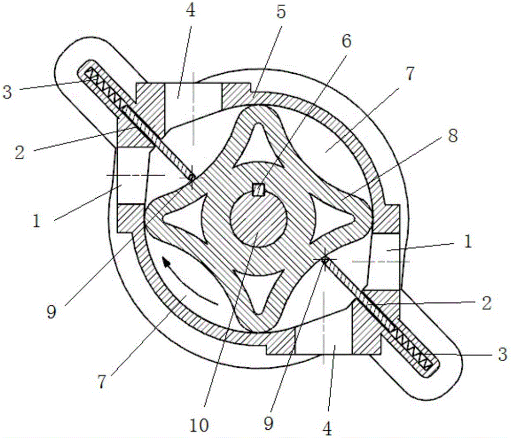
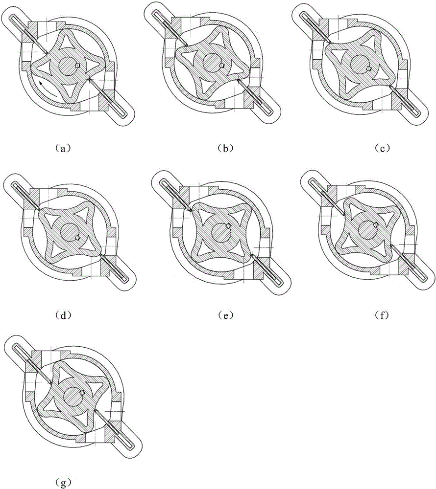
[0014] Refer to attached figure 1 , a skateboard arcuate rotor pump, including a pump body 5 with two slide slots along the axial direction, an arcuate rotor 8, a shaft 10, a key 6, a slide plate 2, and a cylindrical roller 9. When working, the arc-shaped rotor 8 is driven by the key 6 and rotates with the shaft 10. Four chambers 7 are formed between the arc-shaped rotor 8 and the pump body 5. When the chambers 7 turn to meet the slide plate 2, the chambers The chamber is divided into a liquid discharge chamber (communicated with the liquid discharge port 1) and a liquid suction chamber (communicated with the liquid suction port 4) by the slide plate 2. Such as image 3 As shown, with the rotation of the arc-shaped rotor, the volume of the two liquid discharge chambers becomes smaller and smaller, causing the fluid to be squeezed out from the two liquid discharge ports 1, while the volume of the two liquid suction chambers becomes larger and larger, causing the fluid to be sq...


PUM


Abstract

The invention discloses a sliding plate arc surface rotor pump, which comprises a pump body, an arc surface rotor, sliding plates, sliding plate grooves, cylindrical rollers, springs, a rotor shaft and the like. The shape of the arc surface rotor is similar to a rounded concave arc edge regular quadrangle, the two sliding plate grooves are respectively offset on two sides of a pump body center, under the action of spring force, the rollers at the bottom of the sliding plates always maintain contact with the rotor surface, the two sliding plates have opposite acting forces to the rotor, and the acting forces cancel each other out. Two liquid suction ports and two liquid discharge ports are in centrosymmetric arrangement relative to the rotor center, and the rotor borne radial force is balanced. When sealed cavities are apart from the liquid suction ports and the liquid discharge ports, the volume no longer changes, thereby avoiding oil-trapping phenomenon. The friction and wear between the sliding plates and the sliding plate grooves have no influence to the circumferential sealing of the pump. The sliding plate grooves and the sliding plates can scrape off substances attached to the sliding plates and the string rotor respectively. The sliding plate arc surface rotor pump is especially suitable for transportation of high viscosity and adsorptive fluid.

Description

technical field [0001] The invention relates to a sliding plate cambered rotor pump, in particular to a fluid conveying pump which uses a sliding plate to isolate the suction and discharge areas, belongs to the technical field of fluid conveying equipment, and is especially suitable for conveying high-viscosity or even absorptive fluids. Background technique [0002] Vane pump is a widely used fluid conveying machinery, which mainly includes pump body, pump cover, rotor, vane, distribution plate, pump shaft and so on. When working, the centrifugal force is used to keep the vanes in contact with the inner surface of the pump body outward along the rotor groove, thereby forming a sealed cavity. With the rotation of the rotor, the volume of the cavity changes, so that the fluid is continuously sucked and discharged. [0003] The single-acting vane pump rotor rotates once, and the volume in the cavity changes once. Since the pump body has only one inlet and one outlet, the radia...

Claims


Application Information

Patent Timeline
Patent Type & Authority Applications(China)
IPC IPC(8): F04C2/356F04C13/00F04C15/06F04C15/00
CPCF04C2/3566F04C13/002F04C15/00F04C15/0042F04C15/06
Inventor 邹旻王志洋陈文杰吴良才朱英杰孔德昂
Owner CHANGZHOU UNIV
Why Eureka
Try Eureka