Eureka AIR delivers breakthrough ideas for toughest innovation challenges, trusted by R&D personnel around the world.

A suspension frame with a frameless traction linear motor in the middle and a magnetic levitation train

A linear motor and suspension technology, which is used in electric traction, electric vehicles, vehicle components, etc., can solve the problems of reducing the overall traction capacity of maglev vehicles, affecting the traction capacity of linear motors, and reducing the efficiency of linear motors, so as to achieve reliable dynamic assistance. Support, prevent collision track, reduce the effect of yaw angle

Active Publication Date: 2018-03-02
NAT UNIV OF DEFENSE TECH
View PDF5 Cites 0 Cited by
  • Summary
  • Abstract
  • Description
  • Claims
  • Application Information

AI Technical Summary

Problems solved by technology

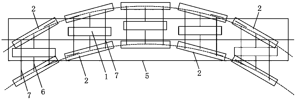
[0004] The bogie installed in the middle of the existing traction linear motor can significantly reduce the limitation on the size of the motor, improve the acceleration and deceleration performance of the vehicle, and effectively reduce the motor air gap and its fluctuation, and improve the traction power and efficiency of the motor; however, in the composition of the vehicle When constrained by the secondary system, there will be a yaw angle between the motor and the track, such as figure 1 shown
Since the bogie in the middle of the existing traction linear motor transmits the thrust of the motor to the left and right suspension modules 2 through the main arm 6, and the main arm 6 is fixed to the traction linear motor 1, this power transmission method will make the traction linear motor 1 Affected by the front and rear positions of the left and right suspension modules 2, the parallelogram formed by the left and right suspension modules 2 and the anti-roll decoupling mechanism 3 changes rhomboidally and cannot maintain a rectangle when cornering, so that the direction of the motor is basically parallel to the car body 5 rather than follow the track
The simulation data shows that the yaw angle between the motor and the track even reaches 6.5°, which will have an adverse effect on the thrust of the motor when passing a curve, thus affecting the traction capacity of the linear motor and reducing the efficiency of the linear motor, thereby reducing The overall towing capacity of the maglev vehicle

Method used


Image

  • A suspension frame with a frameless traction linear motor in the middle and a magnetic levitation train
  • A suspension frame with a frameless traction linear motor in the middle and a magnetic levitation train
  • A suspension frame with a frameless traction linear motor in the middle and a magnetic levitation train

Examples


Embodiment Construction

[0024] The present invention will be described in further detail below in conjunction with the accompanying drawings and specific embodiments.

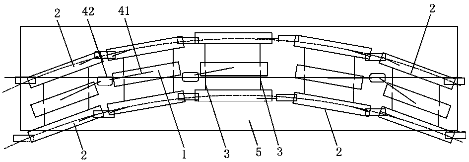
[0025] figure 2 It shows an embodiment of a suspension frame with a frameless traction linear motor in the middle of the present invention, including a traction linear motor 1 and a pair of suspension modules 2, and the traction linear motor 1 is arranged in parallel between the pair of suspension modules 2 , both sides of the traction linear motor 1 are provided with at least two sets of anti-roll decoupling mechanisms 3, the anti-roll decoupling mechanisms 3 are arranged longitudinally along the traction linear motor 1, and the anti-roll decoupling mechanisms 3 include two oppositely arranged anti-roll beams 31 and an anti-roll rod 32, the two ends of the anti-roll beam 31 are respectively hinged on the traction linear motor 1 and the suspension module 2, one end of the anti-roll rod 32 is hinged between the two anti-roll beams 31,...


PUM


Abstract

The invention discloses a framework-free type levitation chassis with a traction linear motor arranged in the center and a magnetically levitated train. The levitation chassis comprises the traction linear motor and a pair of levitation modules, wherein the traction linear motor is arranged between the levitation modules in parallel, and the two sides of the traction linear motor are each provided with at least two sets of anti-rolling decoupling mechanisms. The anti-rolling decoupling mechanisms are arranged in the longitudinal direction of the traction linear motor. Each anti-rolling decoupling mechanism comprises two anti-rolling beams arranged oppositely and an anti-rolling pull rod. The two ends of each anti-rolling beam are hinged to the traction linear motor and the corresponding levitation module correspondingly, one end of each anti-rolling pull rod is hinged to the corresponding two anti-rolling beams, and the other end of each anti-rolling pull rod is hinged to the traction linear motor. The magnetically levitated train comprises a plurality of train bodies and a plurality of framework-free type levitation chassis with the traction linear motors arranged in the center, and the train bodies are mounted on the levitation chassis. The framework-free type levitation chassis with the traction linear motor arranged in the center and the magnetically levitated train have the advantages that the structure is simple, installation and maintenance are convenient, traction efficiency is high, and the turning capacity is high.

Description

technical field [0001] The invention relates to the technical field of maglev trains, in particular to a suspension frame with a frameless traction linear motor in the middle and a maglev train. Background technique [0002] The main difference between maglev vehicles and ordinary wheel-rail vehicles is the generation mechanism of traction force, guiding force and vehicle support force. The non-contact electromagnetic force between the on-board electromagnet of the maglev vehicle and the inverted U-shaped track replaces the supporting force and guiding force generated by contact between the wheel and the track of the wheel-rail vehicle; the non-contact electromagnetic force between the primary and secondary of the linear motor Traction replaces the adhesion between the wheel and rail. The traction force generated by the linear motor is not limited by the wheel-rail adhesion, and its climbing ability and curve passing ability are much higher than those of traditional wheel-r...

Claims


Application Information

Patent Timeline
Patent Type & Authority Patents(China)
IPC IPC(8): B60L13/10B60L13/08
CPCB60L13/08B60L13/10
Inventor 刘耀宗向湘林邓文熙龚朴龙志强
Owner NAT UNIV OF DEFENSE TECH
Why Eureka
Eureka Blog
Learn More