Pump number control method, pump number control device, pump system, heat source system, and recording medium
A control method and heat medium technology, applied in the direction of pump device, pump control, pump, etc., can solve the problem of additional start-up pump
- Summary
- Abstract
- Description
- Claims
- Application Information
AI Technical Summary
Problems solved by technology
Method used
Image
Examples
no. 1 approach
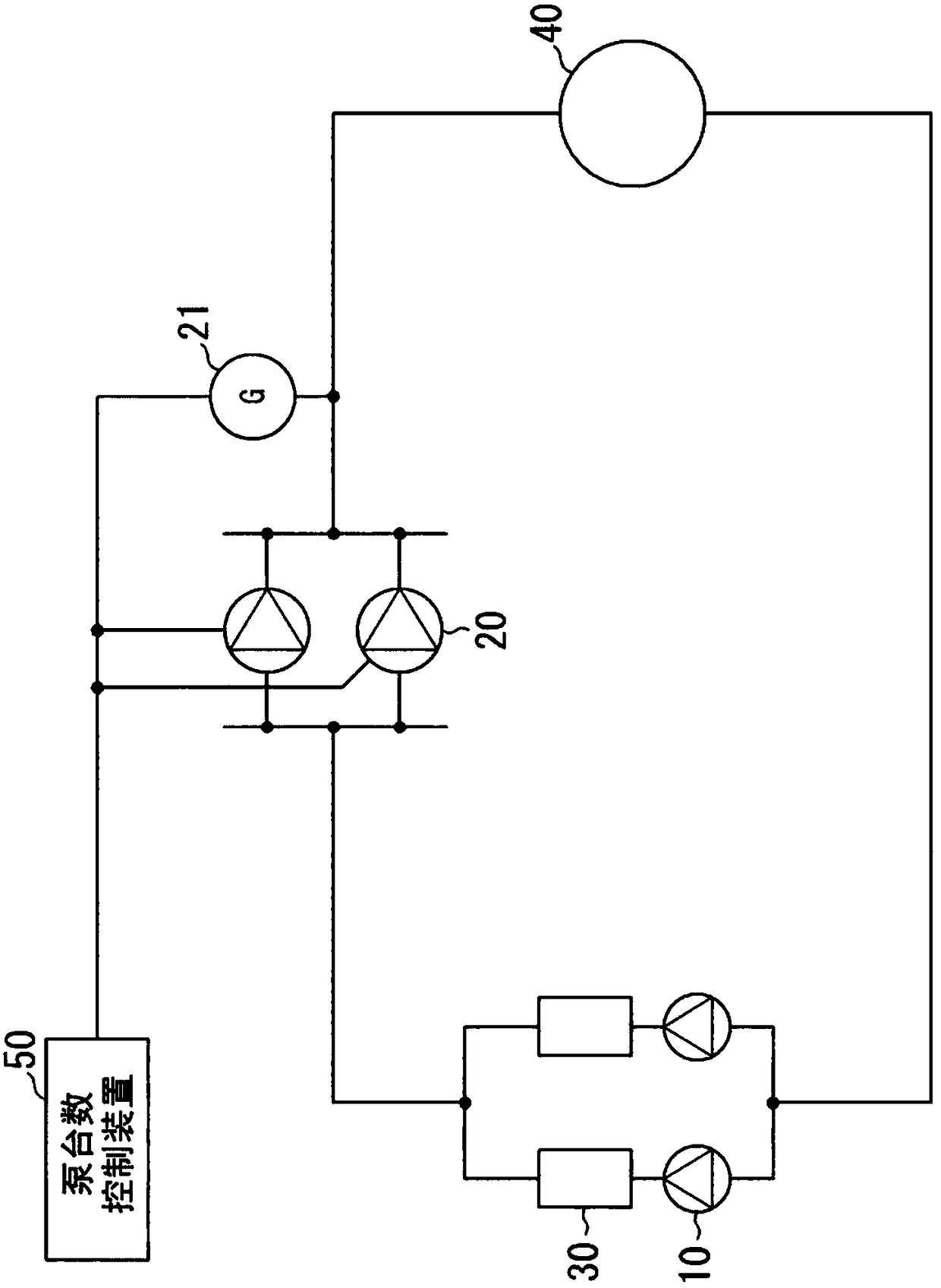
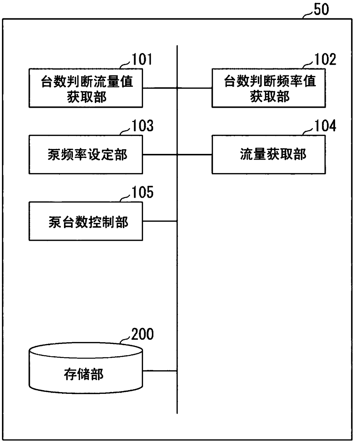
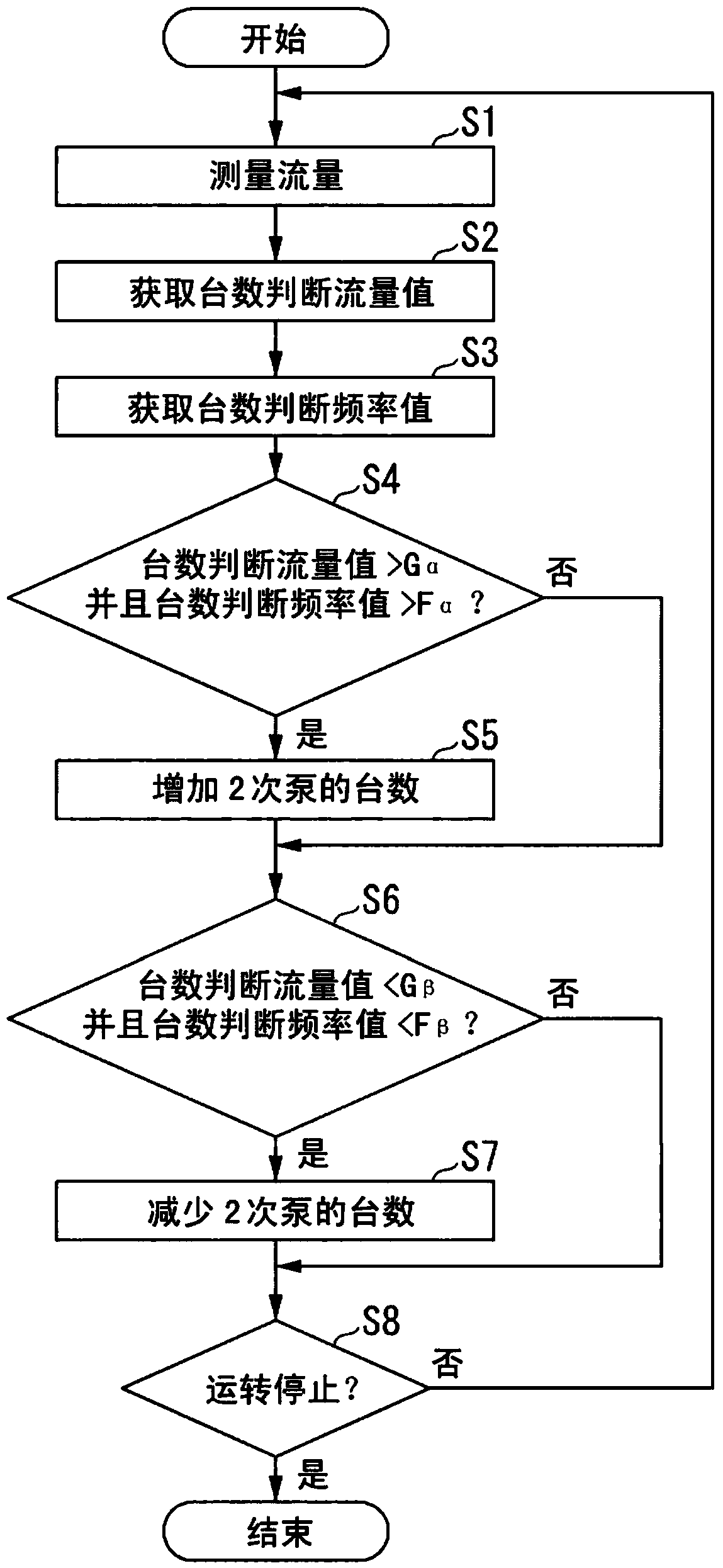
[0041] Below, refer to Figure 1 ~ Figure 3The heat source system of the first embodiment of the present invention will be described.
[0042] figure 1 It is a schematic diagram of the heat source system of 1st Embodiment of this invention.
[0043] Such as figure 1 As shown, the heat source system of this embodiment includes a heat source machine 30 , a primary pump 10 , a secondary pump 20 , a load 40 , a flow meter 21 , and a pump number control device 50 .
[0044] The heat source unit 30 is a device that supplies a cooling or heating heat medium such as water to a load. The primary pump 10 pressure-feeds the heat medium to the heat source machine 30. The heat source unit 30 is a device that supplies a cooling or heating heat medium such as water to a load. In the heat source system of the present embodiment, a plurality of combinations of the heat source machine 30 and the primary pump 10 may be provided in parallel. In the drawing, a state in which a plurality of p...
no. 2 approach
[0117] Below, refer to Figure 6-9 Next, a heat source system according to a second embodiment of the present invention will be described.
[0118] The second embodiment relates to an embodiment for performing more stable pump operation by preventing repetition of increase and decrease in the number of pumps in addition to the first embodiment.
[0119] Figure 6 It is a functional block diagram of the pump number control device of this embodiment.
[0120] The pump number control device 50 of this embodiment differs from the first embodiment in that it includes a pump pressure head acquisition unit 107 . Other configurations of this embodiment are the same as those of the first embodiment.
[0121] The pump pressure head acquisition unit 107 acquires the pump pressure head of the secondary pump 20 currently in operation of the secondary pump 20 and the pump pressure head after the increase or decrease of the secondary pump based on the Q-H characteristic stored in the stor...
no. 3 approach
[0169] Below, refer to Figure 10-11 A heat source system according to a third embodiment of the present invention will be described.
[0170] Like the second embodiment, the third embodiment relates to an embodiment for performing more stable pump operation by preventing repetition of the increase and decrease in the number of pumps in the first embodiment.
[0171] Figure 10 It is a functional block diagram of the pump number control device 50 of this embodiment.
[0172] The pump number control device 50 of this embodiment differs from the first embodiment in that it includes a pump frequency estimated value acquisition unit 108 . Other configurations of this embodiment are the same as those of the first embodiment.
[0173] The pump frequency estimated value acquisition unit 108 acquires the increased pump frequency estimated value and the decreased pump frequency estimated value as the estimated frequency after the increase or decrease in the number of secondary pumps...
PUM
 Abstract
Description
Claims
Application Information
 - R&D
- Intellectual Property
- Life Sciences
- Materials
- Tech Scout
- Unparalleled Data Quality
- Higher Quality Content
- 60% Fewer Hallucinations
Browse by: Latest US Patents, China's latest patents, Technical Efficacy Thesaurus, Application Domain, Technology Topic, Popular Technical Reports.
© 2025 PatSnap. All rights reserved.Legal|Privacy policy|Modern Slavery Act Transparency Statement|Sitemap|About US| Contact US: help@patsnap.com


