
NFC tag interface for energy acquisition and small size optimization

An energy collection, small size technology, applied in the field of NFC tag interface, can solve the problems of complex NFC tag interface design, increase device cost, difficult to achieve NFC energy collection, etc., to improve wireless energy transmission efficiency, reduce development difficulty, equipment Develop flexible effects

Active Publication Date: 2016-08-24
王清斌
View PDF5 Cites 7 Cited by
  • Summary
  • Abstract
  • Description
  • Claims
  • Application Information

AI Technical Summary

Problems solved by technology

When the antenna is small, due to the low coupling coefficient with the NFC reader antenna, coupled with its own low Q value, the efficiency is not high, resulting in a weak load-modulated signal that cannot be reliably received by the NFC reader
Second, because the passive NFC tag interface and NFC reader interface design in the traditional NFC system is directly inherited from RFID, its energy transmission efficiency is very low
However, the disadvantages of active modulation technology are also prominent
First of all, due to the need to actively transmit energy, the signal transmitted by the NFC tag interface must be locked with the frequency and phase of the alternating magnetic field transmitted by the NFC reader interface to avoid signal instability. This solution requires a complex phase-locked loop and phase holding circuit.
This makes the design of the NFC tag interface complicated and the cost rises
Second, the active modulation technique needs to provide energy for the NFC tag interface to transmit, and this technique cannot be used on passive devices such as passive smart cards and tags
Third, due to the complexity that active modulation technology adds to the NFC tag interface, it is difficult to implement NFC energy harvesting for the NFC tag interface using this technology
However, these approaches either increase the cost of the device or limit the performance of the device

Method used


Image

  • NFC tag interface for energy acquisition and small size optimization
  • NFC tag interface for energy acquisition and small size optimization
  • NFC tag interface for energy acquisition and small size optimization

Examples


Embodiment Construction

[0059] In order to make the object, technical solution and advantages of the present invention clearer, the present invention will be further described in detail below in conjunction with the accompanying drawings and embodiments. It should be understood that the specific embodiments described here are only used to explain the present invention, not to limit the present invention.

[0060] On the contrary, the invention covers any alternatives, modifications, equivalent methods and schemes within the spirit and scope of the invention as defined by the claims. Further, in order to make the public have a better understanding of the present utility model, some specific details are described in detail in the detailed description of the present invention below. The present invention can be fully understood by those skilled in the art without the description of these detailed parts.

[0061] The present invention focuses on solving the two main problems of how to effectively use a ...


PUM


Abstract

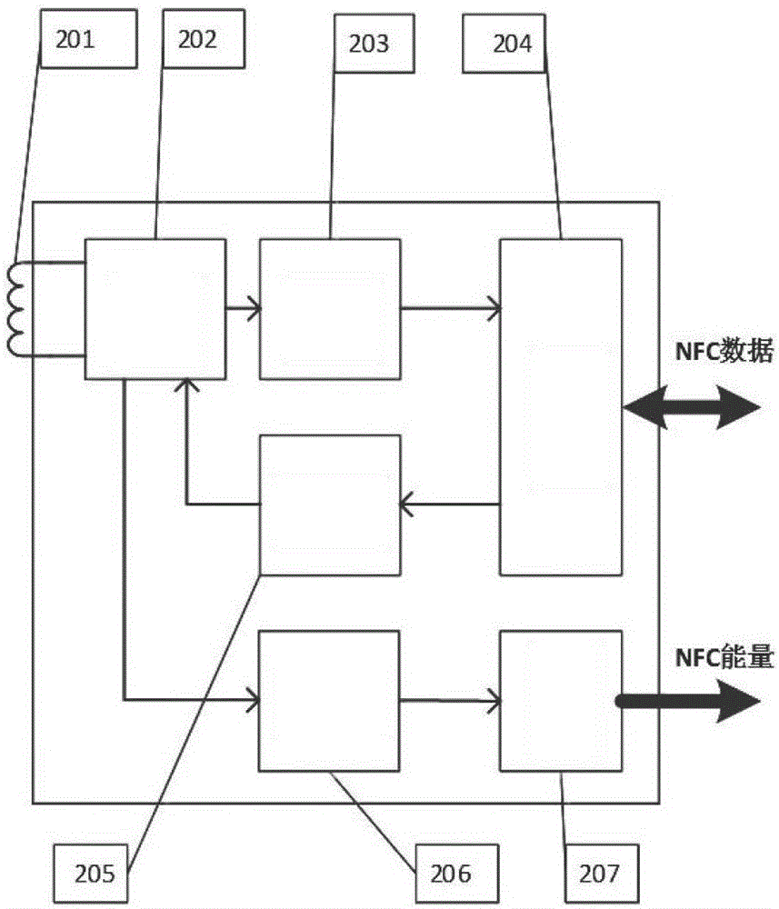
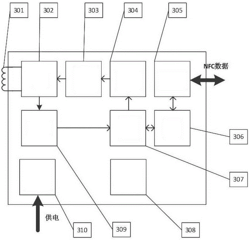
The invention belongs to the technical field of wireless communication, and specifically relates to an NFC tag interface for energy acquisition and small size optimization. The NFC tag interface comprises an antenna, an adjustable matching circuit, a demodulator, a load modulation circuit, a data interface, a rectifier and voltage regulator circuit, and an energy acquisition interface. The antenna, the adjustable matching circuit, the demodulator, the load modulation circuit and the data interface constitute an NFC data receiving circuit. The antenna, the adjustable matching circuit, the rectifier and voltage regulator circuit and the energy acquisition interface constitute an NFC energy receiving circuit. The beneficial affect are as follows: an NFC communication interface is allowed to use a small antenna without affecting the NFC communication performance; by using a small antenna, equipment development is very flexible, and the difficulty in NFC system development is reduced greatly; and the application scope of NFC communication interfaces at present and in the next few years is expanded greatly.

Description

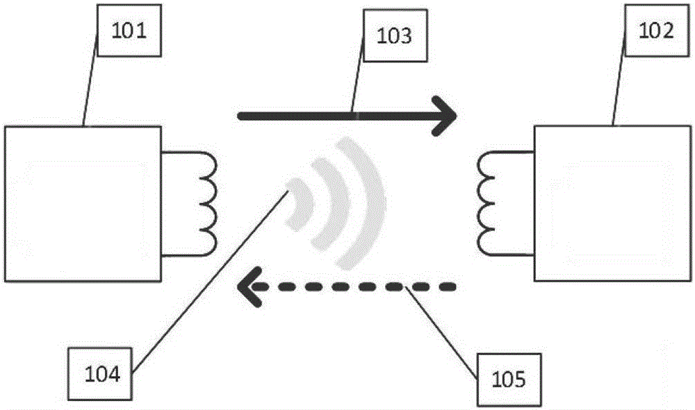
technical field [0001] The invention belongs to the technical field of wireless communication, and in particular relates to an NFC tag interface optimized for energy collection and small size. Background technique [0002] NFC (Near Field Communication) technology is an emerging short-distance secure communication technology in recent years. It uses a magnetic field with a fast attenuation rate in space as the medium for transmitting information, realizing a communication distance of only a few centimeters, and has the advantages of high safety and convenient use. [0003] like figure 1 As shown, there are two common NFC communication interfaces, namely NFC reader interface (Reader) 101 and NFC tag interface (Tag) 102 . Typical NFC communication takes place between these two interfaces. NFC is a half-duplex two-way communication, including two links, namely the reader-to-tag link 103 and the tag-to-reader link 105, each of which is responsible for one communication direct...

Claims


Application Information

Patent Timeline
Patent Type & Authority Applications(China)
IPC IPC(8): H04B5/00
CPCH04B5/77H04B5/79H04B5/00
Inventor 王清斌
Owner 王清斌
Learn More