Road surface detection system and vehicle
A road detection and vehicle technology, applied in the field of vehicles, can solve the problem of high detection cost and achieve the effect of reducing detection cost
- Summary
- Abstract
- Description
- Claims
- Application Information
AI Technical Summary
Problems solved by technology
Method used
Image
Examples
Embodiment 1
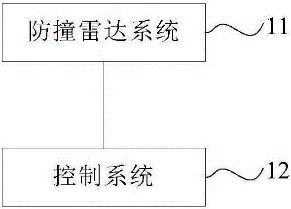
[0018] figure 1 A schematic structural diagram of an embodiment of the road surface detection system provided by the present invention. The road surface detection system of the embodiment of the present invention can be applied to various vehicles. Such as figure 1 As shown, the road surface detection system in the embodiment of the present invention may specifically include a collision avoidance radar system 11 and a control system 12 arranged on the vehicle. in:
[0019] The anti-collision radar system 11 is used to measure the distance data between the chassis of the vehicle and the road surface, and send the distance data to the control system 12 .
[0020] The control system 12 is configured to determine that the road surface is a bumpy road surface if the change of the distance data exceeds a preset distance change value.
[0021] Specifically, when the vehicle is driving on a normal road, the distance data between the vehicle's chassis and the road will not fluctuat...
Embodiment 2
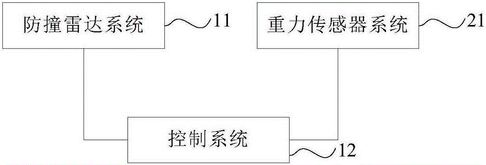
[0024] figure 2 A structural schematic diagram of another embodiment of the road surface detection system provided by the present invention. The road surface detection system of the embodiment of the present invention can be applied to various vehicles. Such as figure 2 As shown, the road surface detection system of the embodiment of the present invention is figure 1 A possible implementation of the road surface detection system of the shown embodiment, in figure 1 On the basis of the illustrated embodiment, a gravity sensor (Gravity-Sensor, G-Sensor for short) system 21 provided on the vehicle may also be included.
[0025] The G-Sensor system 21 is used to detect the driving azimuth data of the vehicle and send the driving azimuth data to the control system 12 .
[0026] Correspondingly, the control system 12 may be specifically configured to: determine that the road surface is a bumpy road surface if the change of the driving azimuth angle data exceeds a predetermined...
Embodiment 3
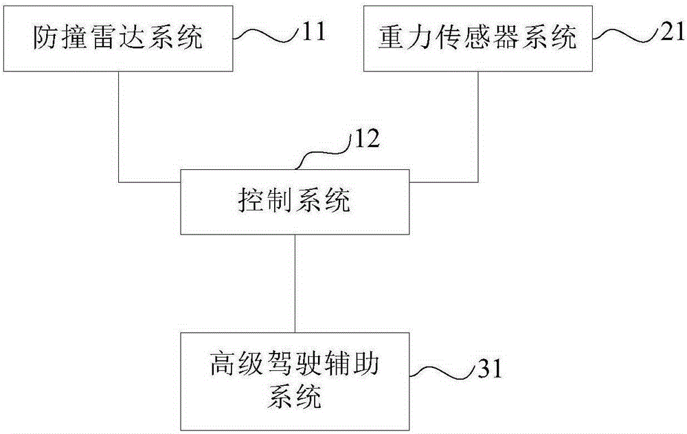
[0031] image 3 A structural schematic diagram of another embodiment of the road surface detection system provided by the present invention. The road surface detection system of the embodiment of the present invention can be applied to various vehicles. Such as image 3 As shown, the road surface detection system of the embodiment of the present invention is figure 2 A possible implementation of the road surface detection system of the shown embodiment, in figure 2 On the basis of the illustrated embodiment, an advanced driver assistant system (Advance Driver Assistant System, referred to as ADAS) 31 provided on the vehicle may also be included.
[0032] ADAS 31 is used to detect the ADAS data of the vehicle and send the ADAS data to the control system 12 .
[0033] Correspondingly, the control system 12 can be specifically used to: determine whether the vehicle is in the state of switching lanes or overtaking on a curve according to the ADAS data; In the overtaking sta...
PUM
 Abstract
Description
Claims
Application Information
 - R&D Engineer
- R&D Manager
- IP Professional
- Industry Leading Data Capabilities
- Powerful AI technology
- Patent DNA Extraction
Browse by: Latest US Patents, China's latest patents, Technical Efficacy Thesaurus, Application Domain, Technology Topic, Popular Technical Reports.
© 2024 PatSnap. All rights reserved.Legal|Privacy policy|Modern Slavery Act Transparency Statement|Sitemap|About US| Contact US: help@patsnap.com


