
Calibration device and calibration method for optical path difference tester

A calibration device and optical path difference technology, which is applied in the direction of instruments, can solve the problems of low precision, high requirements, and high cost, and achieve the effects of strong engineering practicability, intuitive measurement calibration, and low cost

Active Publication Date: 2018-03-06
CHINA ELECTRONICS TECH GRP NO 23 RES INST
View PDF8 Cites 0 Cited by
  • Summary
  • Abstract
  • Description
  • Claims
  • Application Information

AI Technical Summary

Problems solved by technology

[0003] The existing calibration devices and calibration methods cannot meet the high-precision measurement requirements of the optical path difference tester; at present, the optical fiber length measurement methods mainly include backscattering method, pulse method and phase shift method, but each has the following defects:
[0004] (1) The backscattering method mainly includes optical time domain reflectometer OTDR and optical frequency domain reflectometer OFDR, in which OTDR accuracy is not high; OFDR has high requirements on light source, detection and processing equipment, and complex structure;
[0005] (2) The accuracy of the pulse method and phase shift method is restricted by the detector and data processing, which requires high equipment such as optical network analyzer and high cost;
[0006] Therefore, in view of the lack of precision in the prior art and the inability to be directly applied to the measurement and calibration of the optical path difference tester, it is necessary to provide a calibration device and calibration method for the optical path difference tester

Method used


Image

  • Calibration device and calibration method for optical path difference tester
  • Calibration device and calibration method for optical path difference tester

Examples


Embodiment Construction

[0043] In order to make the technical means, technical features, invention objectives and technical effects realized by the present invention easy to understand, the present invention will be further described below in conjunction with specific illustrations.

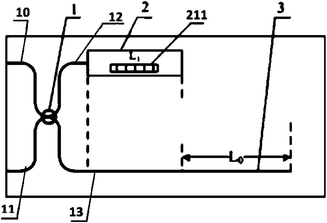
[0044] figure 1 It is a schematic structural diagram of a preferred embodiment of the present invention;

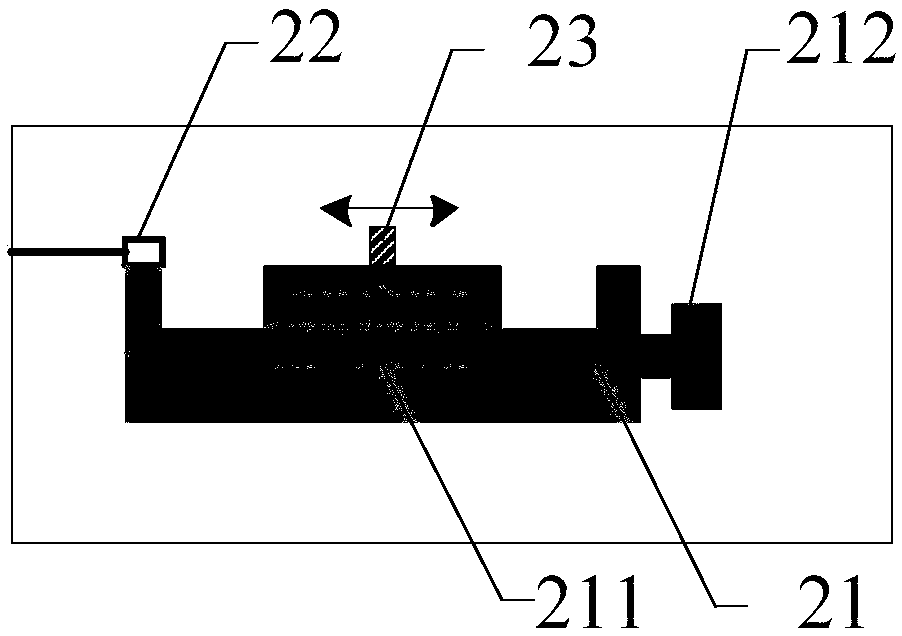
[0045] figure 2 It is a schematic structural diagram of an optical fiber delay line in a preferred embodiment of the present invention.

[0046] Such as figure 1 , figure 2 A calibration device for an optical path difference tester shown includes a coupler 1, a fiber delay line 2 and a standard fiber 3, and the coupler is provided with an input pigtail 10, an output pigtail 11, a first connecting pigtail 12 and a second Connect the pigtail 13, the second connecting pigtail 13 is connected to the standard optical fiber through an optical fiber connector, the end of the standard optical fiber is ground and poli...


PUM


Abstract

The invention discloses a calibration device for an optical path difference test instrument and a calibration method adopting the calibration device. The calibration device comprises a coupler, a fiber delay line and a standard fiber; light emitted by a light source enters the coupler through an input pigtail; after being split, the light enters the fiber delay line and the standard fiber; the fiber delay line includes a displacement device; the displacement device comprises a movable slider and a scale; the fixed end of the displacement device is provided with a collimator; the slider is provided with a reflector; a first optical path is reflected to the coupler through the reflector and is outputted to the optical path difference test instrument through an output pigtail; a second optical path is reflected to the coupler through the tail end of the standard fiber and is outputted to the optical path difference test instrument through the output pigtail; and the first optical path and the second optical path have optical path difference. With the calibration device and the calibration method of the invention adopted, the measurement calibration problem of the optical path difference test instrument can be solved. The uncertainty of the calibration device is lower than 0.1 mm, and the measuring demands of the application of the optical path difference test instrument to an interferometric optical fiber sensor and the like can be satisfied.

Description

technical field [0001] The invention relates to a calibration device and a calibration method, in particular to a calibration device for an optical path difference tester and a method for using the calibration device. Background technique [0002] In the field of interferometric optical fiber sensors, it is necessary to precisely control the optical path difference between the two interfering optical paths of the sensor to meet the requirements of product consistency and array scale. Interferometric fiber optic sensors are usually in the form of Michelson interferometers. The optical path difference tester is a powerful tool for measuring the optical path difference of the two interfering optical paths of the Michelson interferometer, and the accuracy can be better than 1mm. [0003] The existing calibration devices and calibration methods cannot meet the high-precision measurement requirements of the optical path difference tester; at present, the optical fiber length meas...

Claims


Application Information

Patent Timeline
Patent Type & Authority Patents(China)
IPC IPC(8): G01D18/00
CPCG01D18/00
Inventor 张万经叶蕾陈小宝汤钧施海燕
Owner CHINA ELECTRONICS TECH GRP NO 23 RES INST
Learn More