Bio-oil combustion apparatus

A combustion device and bio-oil technology, applied in the direction of combustion methods, liquid fuel supply/distribution, etc., can solve the problems of inability to ensure the stability and full combustion of bio-oil, poor stability of bio-oil, and change of bio-oil properties, so as to improve operational safety performance, ensure stability, and accelerate evaporation

Inactive Publication Date: 2016-08-24
CHONGQING DANQING BIOLOGY TECH
View PDF0 Cites 1 Cited by
  • Summary
  • Abstract
  • Description
  • Claims
  • Application Information

AI Technical Summary

Problems solved by technology

Bio-oil is a mixture of various hydrocarbons, generally containing 20-30% water, so it is not easy to be ignited; moreover, bio-oil contains various organic acids such as formic acid and acetic acid, which are harmful to direct contact with biological Oil storage tanks, oil pipelines, oil pumps in pipelines, and combustion equipment all have strong corrosion effects. Therefore, compared with the storage, transportation, and combustion equipment of ordinary fuel oil, bio-oil storage and combustion equipment needs It has stronger corrosion resistance; in addition, the viscosity of bio-oil is relatively high, which is between heavy oil and light oil, and it cannot reduce the viscosity by heating, so it cannot be atomized by heating; at the same time, because bio-oil The stability is poor. If the viscosity is reduced by simple heating, the properties of bio-oil will be changed, and its combustion performance will also be affected; therefore, the burner specially designed for ordinary fuel oil (heavy oil or light oil) cannot guarantee the stability of bio-oil And full combustion, can not be used as a bio-oil burner

Method used


Image

  • Bio-oil combustion apparatus

Examples


Embodiment 1

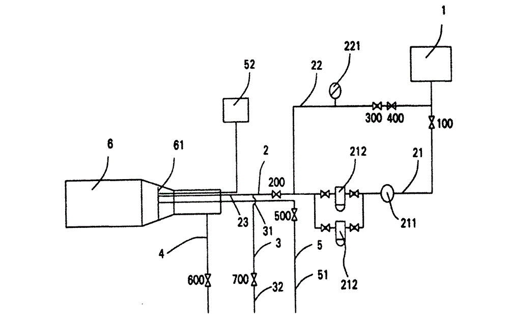
[0020] Please refer to figure 1 The bio-oil combustion device of the present invention includes an oil storage tank 1, an atomization system 3 for atomizing and decomposing bio-oil before combustion, a stable combustion chamber 6 for directly burning bio-oil, an auxiliary ignition system 5, and a combustion air distribution system 4 and the delivery system 2 that transports the bio-oil from the storage chamber to the stable combustion chamber 6.

[0021] The oil storage tank 1 is made of acid-resistant material, such as stainless steel. The delivery system 2 includes a first oil delivery passage 21 and an oil return passage 22 connected in parallel between the oil storage tank 1 and the atomization system 3 and a second oil passage connected between the atomization system 3 and the combustion chamber 6 The oil delivery passage 23, the end of the second oil delivery passage 23 extending into the combustion chamber 6 is connected with a nozzle (not shown). An oil pump 211 for ...

Embodiment 2

[0030] As another kind of scheme of the present invention, other parts are identical with embodiment 1, and difference is:

[0031] The oil pump 211 and the filter 212 on the first oil delivery channel 21 can exchange the front and rear positions according to the layout requirements of the device, and can also realize the function of delivering bio-oil.

[0032] The number of parallel-connected filters 212 on the first oil delivery passage 21 is two or more.

[0033] Other high combustion value gases can be selected instead of liquefied natural gas to be delivered to the stable combustion chamber 6 through the auxiliary ignition system 5, all of which can achieve the same ignition effect.


PUM


Abstract

The invention discloses a bio-oil combustion apparatus. The bio-oil combustion apparatus comprises a bio-oil storage tank, an atomizing system, a stable combustion chamber, an auxiliary ignition system, a combustion air distribution system for providing combustion-supporting air for bio-oil combustion, and a conveying system for conveying bio-oil into the stable combustion chamber from the bio-oil storage tank. The conveying system comprises a first bio-oil conveying duct, a bio-oil return duct and a second bio-oil conveying duct, wherein the first bio-oil conveying duct and the bio-oil return duct are connected between the bio-oil storage tank and the atomizing system and arranged in parallel, and the second bio-oil conveying duct is connected between the atomizing system and the stable combustion chamber. The bio-oil combustion apparatus can achieve constant and stable combustion of the bio-oil and fully release energy of the bio-oil, and is convenient to maintain and long in service life.

Description

technical field [0001] The invention relates to a combustion device, in particular to a bio-oil combustion device. Background technique [0002] With the continuous development of the world economy, energy and environmental issues have become increasingly prominent. The main energy sources currently used by human beings are oil, natural gas and coal. According to the statistics of the International Energy Agency, the lifespan of these three kinds of energy for human exploitation on the earth is only 40 years, 50 years and 240 years respectively. The development of new energy has become a major issue related to the sustainable development of human society. [0003] Biomass energy is converted from solar energy stored in plants through photosynthesis of plants and solar energy. It is estimated that the annual energy stored in plants is equivalent to 10 times the world's main fuel consumption, while the utilization of energy as energy is less than 1% of the total. Through b...

Claims


Application Information

Patent Timeline
Patent Type & Authority Applications(China)
IPC IPC(8): F23K5/02F23K5/18F23K5/22
Inventor 何飞马春林
Owner CHONGQING DANQING BIOLOGY TECH
Why Eureka
Try Eureka