
Lint hooking tool of tufting machine

A technology of hooking knife and tufting machine, which is applied in the field of hooking knife, and can solve problems such as being unable to escape from the upper horizontal edge, and being unable to produce looped pile products without cutting the pile loops.

Inactive Publication Date: 2016-08-24
ZHEJIANG DADA HOMETEXTILE
View PDF15 Cites 0 Cited by
  • Summary
  • Abstract
  • Description
  • Claims
  • Application Information

AI Technical Summary

Problems solved by technology

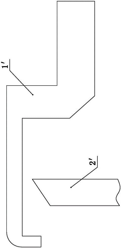
[0002] At present, the existing hooking knife 1' such as figure 1 As shown, it includes an upper horizontal side and a lower horizontal side, the front end of the upper horizontal side is bent downward to form a barb, the rear end of the upper horizontal side is connected with the front end of the lower horizontal side, and the rear end of the lower horizontal side The part is the plug-in tail, so that when hooking, the upper horizontal edge is inserted into the pile loop, and the wool is hooked through the barb part, but because the pile loop cannot be removed from the upper horizontal edge after being hooked, the hooking knife 1 ′ is a continuous reciprocating movement, that is, after hooking a pile loop, the hooking knife 1′ needs to be stretched out again to hook the next pile loop, so once the hooked pile loop cannot be released from the upper horizontal edge in time, then the It will accumulate on the hooking knife 1', so that the hooking knife 1' can no longer be hooked. In the prior art, the usual method is to set up a straight knife 2' to drive the straight knife 2' to move up and down , forming a shear with the hooking knife 1', and cutting the loops, so that the loops can be released from the hooking knife 1' in time, which is convenient for the hooking knife 1' to carry out the next hooking operation, but this will cause the current Some tufting machines can only produce cut pile products that cut the pile loops, but cannot produce loop pile products that do not cut the pile loops

Method used


Image

  • Lint hooking tool of tufting machine
  • Lint hooking tool of tufting machine

Examples


Embodiment Construction

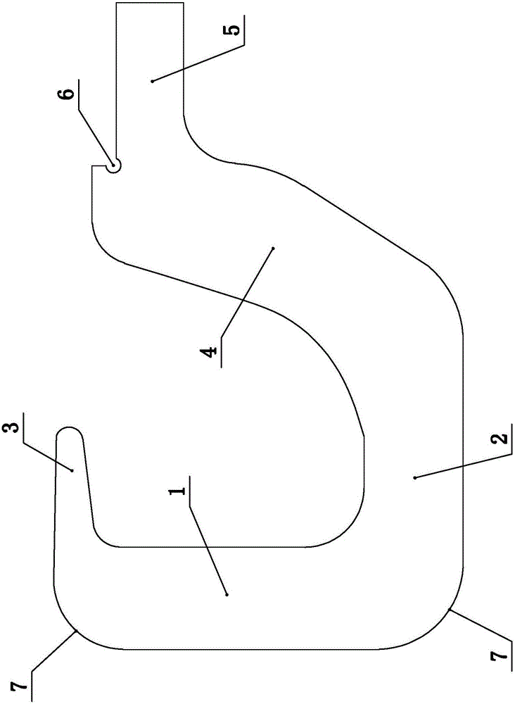
[0010] Such as figure 2 Shown is a tufting knife of a tufting machine, including a knife beam, the knife beam has a vertical section 1 and a transverse section 2, and the upper end of the vertical section 1 is bent and extended to form a The barb part 3, the lower end of the vertical section 1 is connected with the front end of the transverse section 2, the rear end of the transverse section 2 is connected with a smooth section 4 extending obliquely upward, and the smooth section 4 is connected with a backward curved Fold the extended plug tail 5. A positioning notch 6 is provided at the joint between the plug tail portion 5 and the smooth section 4 . The upper and lower ends of the vertical section 1 are rounded 7 .

[0011] With the hooking knife provided by the present invention, the barb portion 3 moves backward after hooking the pile loop, and then moves forward again to pick up the next pile loop, the hooked pile loop will take advantage of the trend from the barb por...


PUM


Abstract

The invention discloses a lint hooking tool of a tufting machine. The lint hooking tool comprises a tool beam, wherein the tool beam is provided with a vertical section and a transverse section; the upper end part of the vertical section is bent backward and extends to form a reversed hook part; the lower end part of the vertical section is connected with the front end part of the transverse section; the rear end part of the transverse section is connected with a smooth section which extends upward obliquely; and the smooth section is connected with an inserting tail part which is backward bent and extends. By virtue of the lint hooking tool disclosed by the invention, after the reversed hook part moves backward to hook a lint loop and moves frontward again to hook the next lint loop, the hooked lint loop is released from the reversed hook part and slides out upward along the smooth section, so that people can realize lint hooking operation under the condition that the lint loop is not cut by people.

Description

technical field [0001] The invention relates to a tufting machine, in particular to a hooking knife of the tufting machine. Background technique [0002] At present, the existing hooking knife 1' such as figure 1 As shown, it includes an upper horizontal side and a lower horizontal side, the front end of the upper horizontal side is bent downward to form a barb, the rear end of the upper horizontal side is connected with the front end of the lower horizontal side, and the rear end of the lower horizontal side The part is the plug-in tail, so that when hooking, the upper horizontal edge is inserted into the pile loop, and the wool is hooked through the barb part, but because the pile loop cannot be removed from the upper horizontal edge after being hooked, the hooking knife 1 ′ is a continuous reciprocating movement, that is, after hooking a pile loop, the hooking knife 1′ needs to be stretched out again to hook the next pile loop, so once the hooked pile loop cannot be rele...

Claims


Application Information

Patent Timeline
IPC IPC(8): D05C15/22
CPCD05C15/22
Inventor 林忠义
Owner ZHEJIANG DADA HOMETEXTILE
Learn More