Microphone circuit, system and headset
A microphone and circuit technology, applied in the field of circuits and systems, can solve problems such as interface resource shortage, and achieve the effect of reducing output pins
- Summary
- Abstract
- Description
- Claims
- Application Information
AI Technical Summary
Problems solved by technology
Method used
Image
Examples
Embodiment 1
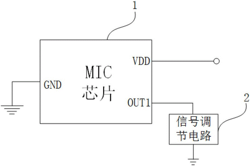
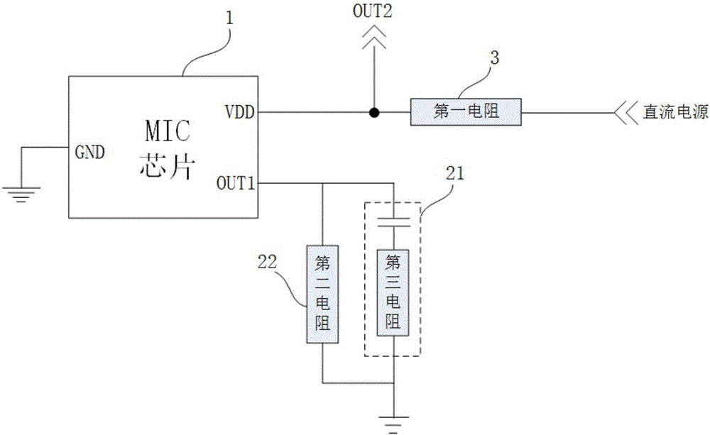
[0019] Such as figure 2 As shown, it is one of the structural diagrams of the microphone circuit in Embodiment 1 of the present invention. The microphone circuit includes: a microphone (MIC) chip 1 and a signal conditioning circuit 2. The microphone chip 1 has a DC power input terminal VDD, a first The signal output terminal OUT1 is connected to the ground terminal GND.
[0020] The signal conditioning circuit is connected between the first signal output terminal and the ground, so that an AC signal path is formed between the first signal output terminal and the ground, and is used to output the first signal output terminal The first analog audio signal is superimposed on the DC power input signal at the DC power input terminal for output. Wherein, in the embodiment of the present invention, the microphone chip is preferably a MEMS (Micro Electro Mechanical System) type microphone chip.
[0021] This embodiment makes full use of the virtual short principle of the operationa...
Embodiment 2
[0029] The first embodiment mainly introduces the relevant circuit structure around the MIC chip, and this embodiment will further introduce the relevant circuit structure in the scenario of connecting the above-mentioned microphone circuit to the terminal. Such as Figure 5 As shown, it is a schematic structural diagram of the microphone circuit in Embodiment 2 of the present invention. On the basis of the microphone circuit in Embodiment 1, an interface module 4 is added. Wherein, the second signal output terminal OUT2 is located at the terminal side, and an interface module 4 is provided between the second signal output terminal and the DC power input terminal of the microphone chip.
[0030]Further, a microphone analog-to-digital (ADC) processing module is provided on the terminal side, the microphone analog-to-digital processing module includes a MICBIAS signal output terminal and a microphone signal input terminal, and the DC power supply is the MICBIAS signal output fro...
Embodiment 3
[0033] Such as Image 6 As shown in , it is a schematic structural diagram of a microphone circuit according to Embodiment 3 of the present invention. The difference between the present embodiment and the second embodiment is that the interface module 4 in the present embodiment is an interface module with a structure suitable for forward and reverse insertion.
[0034] Specifically, the interface module may have a first MIC / ground connection pin and a second MIC / ground connection pin having a positive and negative plug-in symmetrical relationship in position. The meaning of the MIC / ground connection pin mentioned here is that the microphone chip is connected to the terminal side only through two wires, one is the ground wire, and the other is used to transmit the DC power input superimposed with the first analog audio signal The transmission line of the signal (can be called the MIC signal transmission line, the output is the second analog audio signal), but due to the possi...
PUM
 Abstract
Description
Claims
Application Information
 - R&D
- Intellectual Property
- Life Sciences
- Materials
- Tech Scout
- Unparalleled Data Quality
- Higher Quality Content
- 60% Fewer Hallucinations
Browse by: Latest US Patents, China's latest patents, Technical Efficacy Thesaurus, Application Domain, Technology Topic, Popular Technical Reports.
© 2025 PatSnap. All rights reserved.Legal|Privacy policy|Modern Slavery Act Transparency Statement|Sitemap|About US| Contact US: help@patsnap.com


