
A power information monitoring system

A monitoring system, power information technology, applied in information technology support system, power network operating system integration, general control system, etc., can solve the problems of no module code data, database saturation, high cost, to ensure real-time transmission, improve Accuracy and easy maintenance

Active Publication Date: 2018-08-21
NORTHEAST DIANLI UNIVERSITY
View PDF6 Cites 0 Cited by
  • Summary
  • Abstract
  • Description
  • Claims
  • Application Information

AI Technical Summary

Problems solved by technology

[0004] (1) All data collection does not include location data, which is poorly targeted, making the accuracy of the entire monitoring result low;
[0005] (2) All data collection does not carry module code data. If one of the data collection modules fails, it is necessary to check the entire monitoring system, which is time-consuming and laborious;
[0006] (3) The collected data is only a single evaluation of the power equipment situation through drawing or preset algorithms, and simulation analysis cannot be performed;
[0007] (4) Only the evaluation results of the situation of the power equipment can be obtained, and then the corresponding solution strategy needs to be manually specified based on experience, and the simulation of the corresponding solution strategy cannot be carried out;
[0008] (5) It is impossible to control the surrounding environment of electric equipment;
[0009] (6) It is necessary to lay the line, which is costly and at the same time, once the line fails, the data transmission cannot be completed
[0010] (7) Due to the limited memory of the database, it is easy to cause the saturation of the database, and it is necessary to manually clear and arrange the data

Method used


Image

  • A power information monitoring system

Examples


Embodiment Construction

[0035] In order to make the objects and advantages of the present invention clearer, the present invention will be further described in detail below in conjunction with the examples.

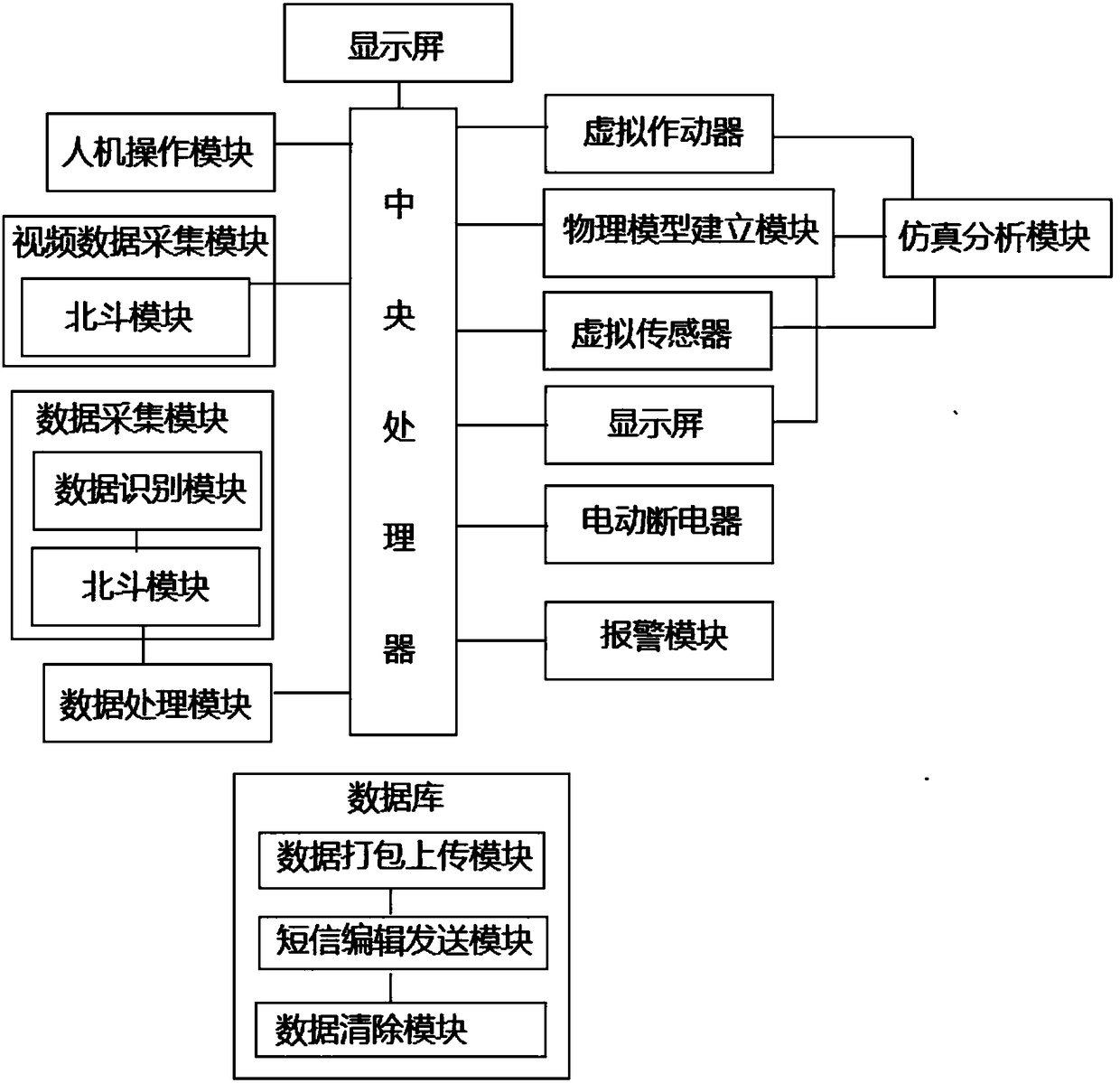
[0036] Such as figure 1 As shown, a kind of power information monitoring system of the present invention comprises:

[0037] A man-machine operation module, which is used for the input of basic information, data calling commands and various control commands of the power equipment to be monitored;

[0038] A data acquisition module, used to collect the current, voltage, power and temperature of the power equipment, as well as the humidity, air pressure and dust concentration in the air around the power equipment, and send the collected data to the data processing module through the Beidou module;

[0039] A video data collection module, which is used to collect video data from the monitoring site through the camera, and send the collected data to the central processing unit through the Beidou mo...


PUM


Abstract

The invention discloses a system for monitoring electric power information. The system is characterized by comprising a man-machine operating module, a data acquisition module, a video data acquisition module, a data processing module, a central processing unit, a physical model establishing module, a virtual actuator, a virtual sensor, a simulation analysis module, an alarm module and an electric circuit breaker; the virtual actuator feeds the result back to the simulation analysis module by cyclically executing simulation analysis, the simulation analysis module automatically extracts data to the virtual sensor, and the virtual sensor displays the analysis result. Remote omni-bearing monitoring of electric power facilities and adjustment and control of the environment around the electric power facilities can be achieved, and remote power failure is achieved under the emergency situation. All the acquired data comprises positioning data, the precision of the monitoring result is improved, later maintenance is convenient, simulation analysis of the situation of the power equipment and analogue simulation of a solving strategy are achieved, cost is reduced, and real-time transmission of the data is guaranteed.

Description

technical field [0001] The invention relates to the technical field of power information monitoring, and relates to a power information monitoring system. Background technique [0002] During power operation, changes in the power grid are prone to occur due to fluctuations in user loads or instability of power generation companies, which need to be dealt with in a timely manner. In the past, traditional power monitoring mainly relied on personnel experience and traditional information communication. High operating experience is required. [0003] At present, the current mainstream power information monitoring system also adopts the remote monitoring mode, but only collects some main power-related information, and does not have more specific information, such as the collection of power, voltage, power, and environmental information. It is not possible to detect abnormal conditions of power facilities from the timing in the central control room, and some risk factors may be m...

Claims


Application Information

Patent Timeline
Patent Type & Authority Patents(China)
IPC IPC(8): G05B19/042H02J13/00
CPCG05B19/0428G05B2219/24024H02J13/00Y02B70/30Y02B90/20Y04S20/00Y04S20/242
Inventor 崔金栋杜文强郑鹊孙遥遥于圆美孙硕
Owner NORTHEAST DIANLI UNIVERSITY
Learn More