Indoor positioning method based on light pattern

An indoor positioning and light pattern technology, applied in the field of IT information, can solve the problems of a large number of positioning targets, low positioning accuracy, and a wide positioning range, and achieve the effect of easy expansion of the positioning range, high positioning accuracy, and stable positioning results.

Inactive Publication Date: 2016-08-17
HUAZHONG UNIV OF SCI & TECH
View PDF6 Cites 13 Cited by
  • Summary
  • Abstract
  • Description
  • Claims
  • Application Information

AI Technical Summary

Problems solved by technology

[0005] In view of the above defects or improvement needs of the prior art, the object of the present invention is to provide an indoor positioning method based on light patterns, wherein through the composition and setting of the key light pattern emitting device and the corresponding indoor positioning method based on light patterns The measurement parameters of the positioning method are improved, which can effectively solve the problem of low indoor positioning accuracy compared with the existing technology. This indoor positioning method can achieve centimeter-level positioning accuracy, and has a large number of positioning targets and a wide positioning range; The indoor positioning method does not have high requirements on the hardware function of the positioning target, and can greatly expand the scope of application

Method used


Image

  • Indoor positioning method based on light pattern
  • Indoor positioning method based on light pattern

Examples


Embodiment 1

[0035] An indoor positioning method based on light patterns, comprising the following steps:

[0036] (1) Set the light pattern emitting device:

[0037] The light pattern emitting device includes a light source, a fan blade and a motor, wherein,

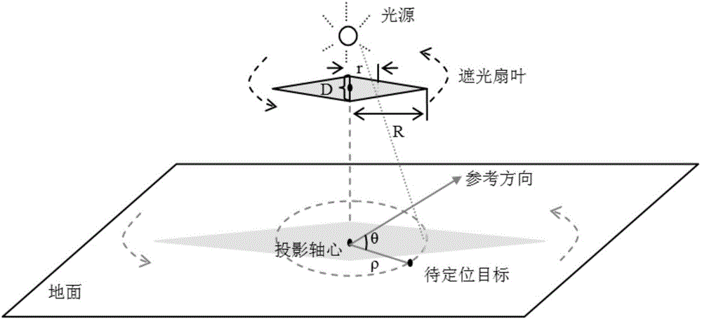
[0038] The fan blade is connected with the motor, and the motor drives the fan blade so that the fan blade rotates at a constant speed around the rotation axis of the fan blade; the line where the rotation axis of the fan blade is located passes through the center of the light source, and the rotation axis is perpendicular to the ground; the light emitted by the light source The shadow is formed on the ground by the fan blade, and the shadow rotates periodically with the fan blade to form a periodic light pattern; on the ground area covered by the shadow periodically, within one cycle of the fan blade rotation, the distance from the fan blade Points on the ground area with different distances from the axis of rotation remain covere...

Embodiment 2

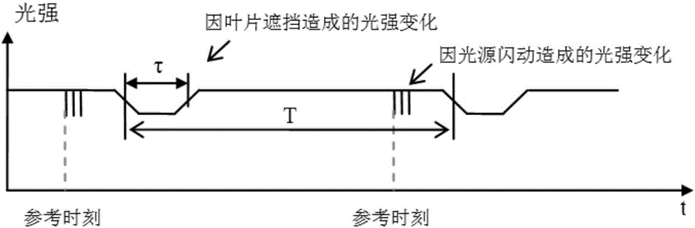
[0046] Taking rhombus fan blades as an example, figure 1 Shown is a light pattern emitting device based on a simple triangular double fan blade, the base of which is D and the height is R. The fan blades in the light pattern emitting device rotate at a constant speed, projecting periodic light patterns on the ground. In addition, the light pattern emitting device controls the light source to turn on and off several times according to a certain rule every time the blade turns to a specific direction, as an indication when the blade rotates to a reference direction.

[0047] The target to be positioned somewhere on the ground, through its photosensitive sensor, detects the light intensity change rule caused by the fan blades periodically blocking the light source and the light source being turned on and off, such as figure 2 shown.

[0048] Next, perform the analysis as follows:

[0049] 1) The object to be positioned extracts the light intensity change law caused by the lig...


PUM


Abstract

The invention discloses an indoor positioning method based on a light pattern. The method comprises the following steps: 1, arranging a light pattern emission apparatus; 2, detecting light signals of an object to be positioned; and 3, positioning the position of the object to be positioned, and obtaining a distance rho from the object to be positioned to a flabellum rotating shaft and a deflection angle theta of the object to be positioned relative to a datum line. According to the invention, through improving composition and arrangement of a light pattern emission apparatus, corresponding measurement parameters of a conventional indoor positioning method based on a light pattern and the like, compared to the prior art, the method provided by the invention has the following advantages: the problem of not high indoor positioning precision can be effectively solved, the indoor positioning method can realize centimeter-grade positioning precision, the quantity of positioning objects is large, and the positioning scope is wide. Besides, the indoor positioning method does not have high requirements for hardware functions of the positioning objects, and the application scope can be greatly expanded.

Description

technical field [0001] The invention belongs to the field of IT information technology, and more specifically relates to an indoor positioning method based on light patterns, which has high positioning accuracy. Background technique [0002] Indoor positioning often requires high accuracy. Existing indoor positioning methods are mainly divided into two categories: positioning methods based on radio signals, and positioning methods based on optical signals. [0003] The current representative solutions for positioning methods based on radio signals include: positioning methods based on ranging information, positioning methods based on detection areas, and positioning methods based on prior knowledge of radio geographical distribution. A common disadvantage of these methods is that because radio signals are easily affected by the environment, the positioning reference provided is unstable, resulting in low positioning accuracy. [0004] The current representative solutions f...

Claims


Application Information

Patent Timeline
Patent Type & Authority Applications(China)
IPC IPC(8): G01S5/16G01S11/12
CPCG01S5/16G01S11/12G01B11/002G01B11/14G01B11/26G06T7/60G01B11/25G01N21/956G01B11/2513
Inventor 郭鹏
Owner HUAZHONG UNIV OF SCI & TECH
Why Eureka
Try Eureka