Test tool for steel plate spring suspension system and test method thereof
A suspension system and leaf spring technology, applied in the field of automotive leaf spring suspension system testing, can solve the problems of high test cost, long cycle, and inability for designers to come up with guiding improvement plans, so as to ensure user safety and ensure delivery quality effect
Active Publication Date: 2016-08-17
东风汽车底盘系统有限公司
View PDF5 Cites 15 Cited by
- Summary
- Abstract
- Description
- Claims
- Application Information
AI Technical Summary
Problems solved by technology
[0003] However, at present, there are only fatigue test methods and standards for leaf springs, stabilizer bars, and thrust rods. For the suspension system composed of leaf springs, stabilizer bars, and thrust bars, there are no ready-made test methods and standards for reference.
In this regard, the fatigue performance of the suspension system is generally tested through real v
Method used
View moreImage
Smart ImageViewing Examples
Examples
 PUM
 Abstract
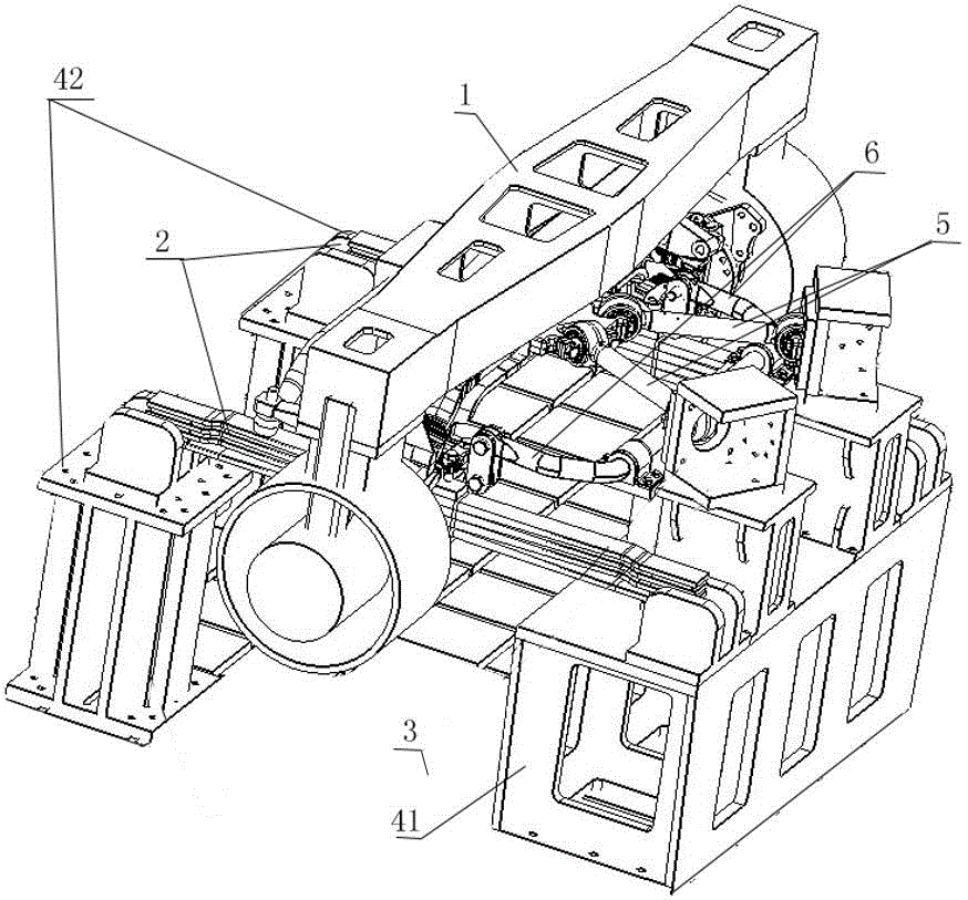
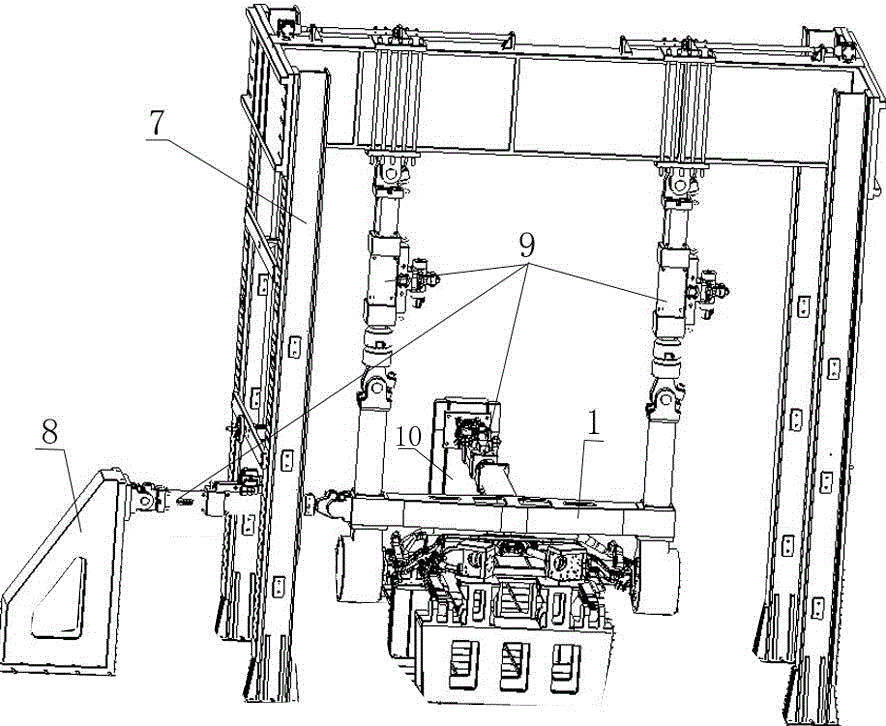
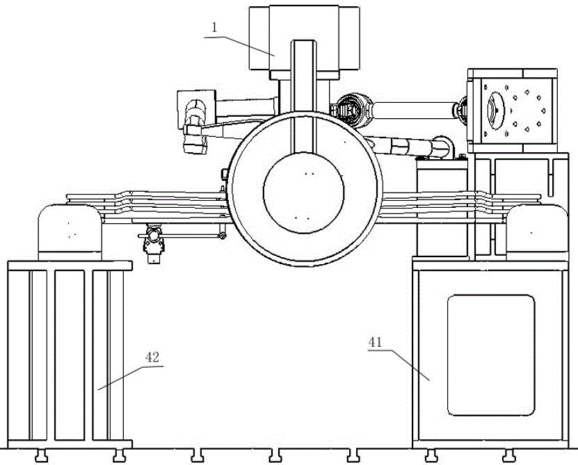
The invention provides a test tool for a steel plate spring suspension system and a test method thereof. The test tool mainly comprises an iron floor, a gantry frame, various brackets and four servo hydraulic systems, wherein the iron floor is used for fixing the steel plate spring suspension system; the four servo hydraulic systems are used for applying loads to the steel plate spring suspension system. During testing, the four servo hydraulic systems are used for applying vertical, transverse and longitudinal loads to the steel plate spring suspension system, and two of the servo hydraulic systems are used for applying vertical loads. According to the test tool for the steel plate spring suspension system, a road test signal driving spectrum can be input through a control system, and the four servo hydraulic systems are controlled to apply loads to the steel plate spring suspension system in order to simulate the stress condition of the steel plate spring suspension system in an actual road test process, so that test data have good reference and are used for testing fatigue features of parts to be tested, and a reliable test measure is provided for the development and test verification of parts.
Description
technical field [0001] The invention relates to the technical field of detection of automobile leaf spring suspension systems, in particular to a test bench for automobile leaf spring suspension systems, which is suitable for stiffness testing and fatigue performance testing of commercial vehicle leaf spring suspension systems. Background technique [0002] The leaf spring suspension system is the most widely used suspension system in the commercial vehicle suspension system. It undertakes various functions such as load bearing, guidance and shock absorption, and is crucial to the technical performance and safety performance of the vehicle. [0003] However, there are currently only fatigue test methods and standards for leaf springs, stabilizer bars, and thrust rods. For the suspension system composed of leaf springs, stabilizer bars, and thrust bars, there are no ready-made test methods and standards for reference. In this regard, the fatigue performance of the suspension ...
Claims
Login to View More Application Information
Patent Timeline
 IPC IPC(8): G01M17/04
CPCG01M17/04
Inventor 王海庆宋志刚易建武蒋路军潘学玉
Owner 东风汽车底盘系统有限公司
- R&D Engineer
- R&D Manager
- IP Professional
- Industry Leading Data Capabilities
- Powerful AI technology
- Patent DNA Extraction
Learn More Browse by: Latest US Patents, China's latest patents, Technical Efficacy Thesaurus, Application Domain, Technology Topic, Popular Technical Reports.
© 2024 PatSnap. All rights reserved.Legal|Privacy policy|Modern Slavery Act Transparency Statement|Sitemap|About US| Contact US: help@patsnap.com


