
Heating furnace

A technology for heating furnaces and furnaces, which is applied to furnaces, lighting and heating equipment, muffle furnaces, etc. It can solve problems such as difficult heating work, less maintenance time, and long cooling time, achieving rapid maintenance and replacement, saving maintenance time, The effect of reducing the maintenance cost

Active Publication Date: 2016-08-17
CHINA NUCLEAR POWER ENG CO LTD
View PDF4 Cites 0 Cited by
  • Summary
  • Abstract
  • Description
  • Claims
  • Application Information

AI Technical Summary

Problems solved by technology

When the material is toxic or radioactive, in order to avoid the spread of toxicity or radioactivity, it is necessary to heat the material in a closed environment; at the same time, due to the existence of radioactivity, it needs as little maintenance time as possible when repairing and replacing the heating equipment. There are heating devices that cannot meet these requirements
In addition, for the batch heating method, since the furnace temperature needs to be lowered to a reasonable temperature before the materials can be taken out, the cooling time is very long, which greatly restricts the improvement of productivity
When the heating element fails, it is difficult for the existing electric heating furnace to continue to complete the heating work

Method used


Image

  • Heating furnace
  • Heating furnace
  • Heating furnace

Examples


Embodiment Construction

[0029] The specific implementation manners of the present invention will be further described in detail below in conjunction with the accompanying drawings.

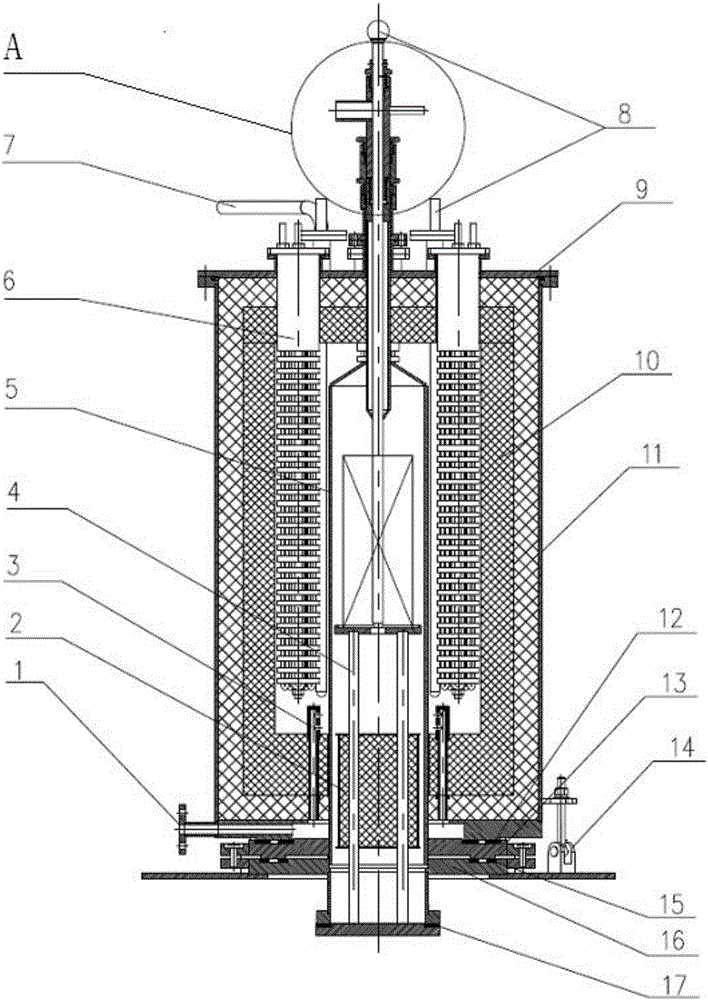
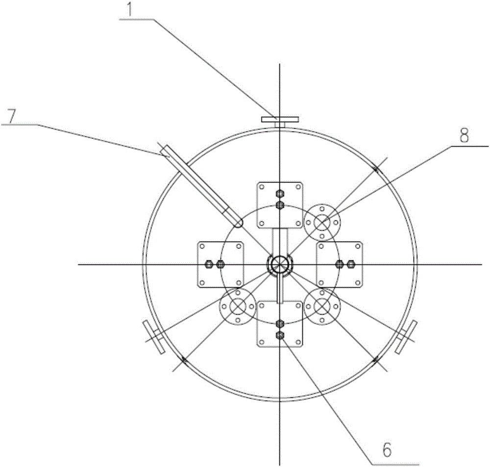
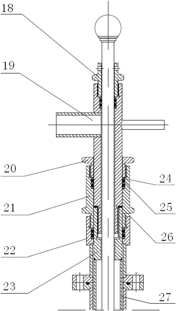
[0030] Such as figure 1 , 2 As shown, it is a schematic structural view of the heating furnace of the present invention. The heating furnace includes a furnace shell 11 with a lower opening and a furnace assembly passing through the furnace shell 11. The furnace assembly includes a furnace chamber 5 and a furnace chamber 5 The hearth 4 that can be raised and lowered inside. The furnace 5 is a bell-shaped thin-wall cavity structure, and its upper part has a furnace top connecting pipe 27, which passes through the top of the furnace shell, and passes between the furnace top connecting pipe 27 and the furnace shell top plate 9. The sealing component is sealed, the lower periphery of the furnace and the bottom of the furnace shell are sealed by the lower sealing component, and the upper sealing component and the lower seal...


PUM


Abstract

The invention relates to a heating furnace comprising a furnace shell with a lower opening and a furnace pipe assembly arranged in the furnace shell in a penetrating manner. The furnace pipe assembly comprises a furnace pipe and a furnace table arranged in the furnace pipe and capable of ascending and descending; the position between the periphery of the lower portion of the furnace pipe and the bottom of the furnace shell is sealed through a lower sealing assembly; the upper portion of the furnace pipe is provided with a furnace pipe top connection pipe; the position between the periphery of the furnace pipe top connection pipe and a top plate of the furnace shell is sealed through an upper sealing assembly; and a plurality of heating elements inserted from the top of the furnace shell are arranged between the inner wall of the furnace shell and the furnace pipe. The heating furnace can heat radioactive materials in a closed environment and can utilize the rest of heating bodies to continue to complete heating under the condition that part of heating bodies lose efficacy; in a weak sealing link, a structure capable of performing double sealing and pressure detection is designed, and sealing reliability is improved; after heating ends, forced cooling can be performed, cooling time is saved, and the production efficiency is improved; and a modular structure is adopted, gradation is distinct, fast overhaul and replacement of parts are achieved, and time is saved.

Description

technical field [0001] The invention belongs to the field of heating equipment, in particular to a heating furnace, which is mainly used for heating toxic or radioactive materials. Background technique [0002] In the chemical industry, it is often necessary to heat materials. When the material is toxic or radioactive, in order to avoid the spread of toxicity or radioactivity, it is necessary to heat the material in a closed environment; at the same time, due to the existence of radioactivity, it needs as little maintenance time as possible when repairing and replacing the heating equipment. There are heating devices that cannot meet these requirements. In addition, for the batch heating method, since the furnace temperature needs to be lowered to a reasonable temperature before the materials can be taken out, the cooling time is very long, which greatly restricts the improvement of productivity. When the heating element breaks down, it is difficult for the existing electr...

Claims


Application Information

Patent Timeline
IPC IPC(8): F27B5/06F27B5/14
CPCF27B5/06F27B5/14F27B2005/064
Inventor 降宇波吴德慧彭思谢非沈琪
Owner CHINA NUCLEAR POWER ENG CO LTD
Learn More