
Biomass cyclone dust removal burner

A cyclone dust removal and burner technology, which is applied in the direction of combustion methods, combustion equipment, and solid fuel combustion, can solve the problems of large combustion smoke and dust, complex structure, and insufficient combustion, and achieve improved combustion rate, improved dust removal performance, and furnace Effect of Fire Purity Improvement

Active Publication Date: 2016-08-17
郭征旭 +1
View PDF9 Cites 18 Cited by
  • Summary
  • Abstract
  • Description
  • Claims
  • Application Information

AI Technical Summary

Problems solved by technology

[0005] Another example is the utility model with the authorized announcement number CN 202229173U disclosing a cyclone dedusting type burner. In order to achieve the dedusting effect, the burner has a special centrifuge chamber, the combustion is more sufficient, and the dedusting effect is also better. Technical problems of insufficient combustion and large combustion smoke
However, due to the addition of centrifugal chambers and other accessories, the entire burner has a large volume, relatively complicated structure, and high cost
[0006] Another example is the utility model with the authorized announcement number CN201391875Y disclosing a blowing air combustion furnace with a built-in independent cyclone dust collector, which is a combination of a dust collector and a burner. Combustion, Combination yields no new functionality

Method used


Image

  • Biomass cyclone dust removal burner
  • Biomass cyclone dust removal burner
  • Biomass cyclone dust removal burner

Examples


Embodiment

[0038] Image 6 It is the simulation effect diagram of the overflow interception of 30 micron dust particles in the present invention, Figure 7It is the simulation effect diagram of the overflow of 30 micron dust particles after the general burner is burned in the prior art. The above two simulation effect diagrams use professional three-dimensional simulation software. It can be compared from the diagrams that the dust retention effect of the present invention is very obvious.

[0039] In the same way, Figure 8 It is the simulation effect diagram of the overflow interception of 50 micron dust particles in the present invention, Figure 9 It is the simulation effect diagram of the overflow of 50 micron dust particles after the general burner is burned in the prior art. It can be compared from the figure that the present invention has a 100% interception effect on 50 micron dust particles.

[0040] Figure 10 It is the actual combustion diagram of biomass material wood in ...


PUM


Abstract

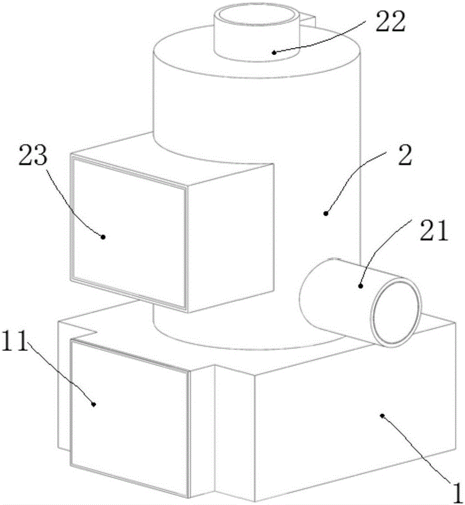
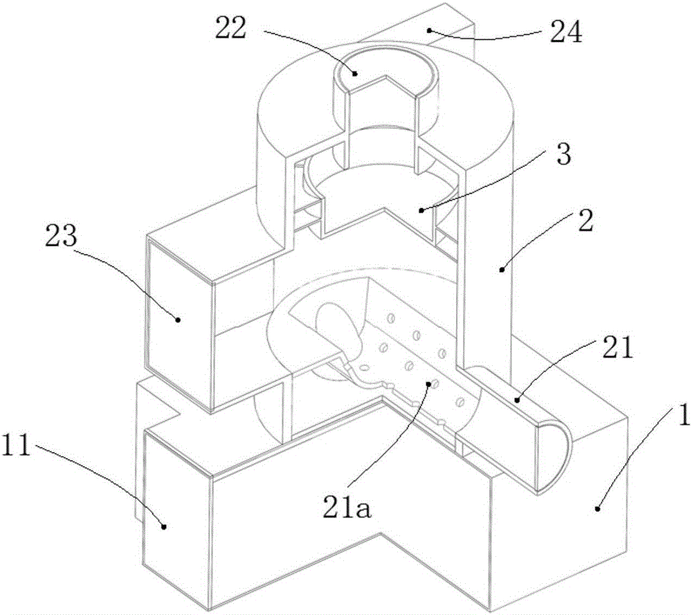
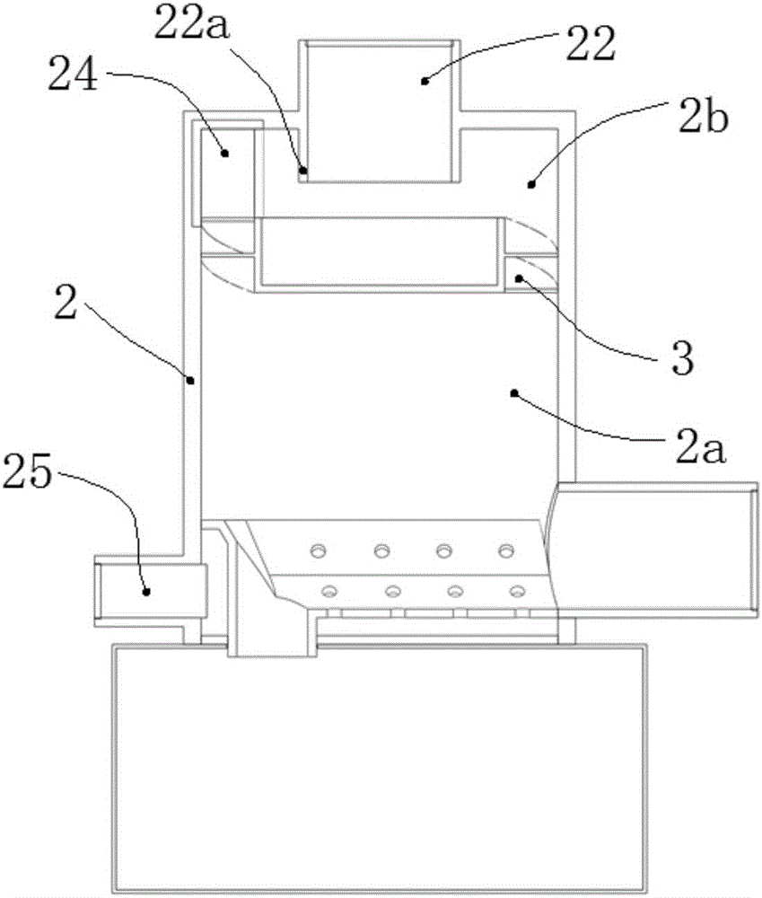
The invention discloses a biomass cyclone dust removal burner. The biomass cyclone dust removal burner is characterized in that a cyclone dust removal burner is arranged at the upper part of a furnace body and at the lower end of a furnace body fire outlet, the cyclone dust removal burner divides the furnace body into a lower burning chamber and an upper burning chamber, a secondary air supply tube consistent with the spiral direction of the cyclone dust removal burner is arranged in the upper burning chamber, the cyclone dust removal burner consists of a concave barrel and S-shaped helical blades arranged outside the concave barrel, the head ends and the tail ends of the S-shaped helical blades are connected at intervals, and the helical angles of the S-shaped helical blades are 15-30 degrees. The biomass cyclone dust removal burner can keep dust particles formed after burning in the upper burning chamber and further enhances the wall-attaching dust collection effect under the centrifugal action, so that the burning effect, the dust removal performance and the fire purity of the burner are remarkably improved, the dust emission concentration is less than or equal to 5 mg / m<3>, the fume blackness reaches Ringelmann 0 grade, dust larger than 30 micrometers cannot overflow, a smoke-free and dust-free effect can be basically achieved, and the specifications of the biomass cyclone dust removal burner are higher than those of like products in the prior art.

Description

technical field [0001] The invention relates to the technical field of fuel equipment, in particular to a burner in this field, in particular to a biomass cyclone dust removal burner. Background technique [0002] In recent years, the development and utilization of biomass energy has attracted more and more attention, and is being gradually promoted and applied. Biomass fuel is a new type of environmentally friendly fuel, which has the characteristics of cleanness, high calorific value, and high combustion rate. The combustion methods of most biomass burners in the prior art are basically the same as those of traditional coal-fired furnaces, either feeding from above or from below. The disadvantages of low efficiency and large combustion smoke. [0003] For example, the utility model of Chinese Patent Publication No. CN201285034Y discloses a biomass burner, which adopts boiling gasification combustion and tangential swirl air distribution design, the combustion rate can re...

Claims


Application Information

Patent Timeline
Patent Type & Authority Applications(China)
IPC IPC(8): F23B10/02F23L1/02F23L9/06F23J15/02
CPCF23B10/02F23J15/027F23J2217/40F23L1/02F23L9/06
Inventor 郭征旭刘宏
Owner 郭征旭
Learn More