A shaft assembly device for a front-wheel-drive automobile transmission assembly

A technology for automotive transmissions and assembling devices, which is applied to transmission parts, components with teeth, belts/chains/gears, etc. It can solve problems such as poor surface quality, damage to oil seals, time-consuming and labor-intensive problems, and achieve the effect of ensuring assembly quality

Active Publication Date: 2018-06-19
CHONGQING TSINGSHAN IND
View PDF6 Cites 0 Cited by
  • Summary
  • Abstract
  • Description
  • Claims
  • Application Information

AI Technical Summary

Problems solved by technology

The disadvantages of this are that the operation process is cumbersome, the labor intensity is high, time-consuming and labor-intensive, and in the manual assembly process, the parts may be bumped and damaged, resulting in poor surface quality and affecting the service life.
More importantly, during manual assembly, the coaxiality requirements of the relevant components and the oil seal cannot be guaranteed, and the risk of damaging the oil seal is extremely high
Because people cannot maintain concentration for a long time, it is inevitable that when the shafting assembly is put into the box, the spline or the journal hits the lip of the oil seal, thereby causing the risk of damage to the oil seal

Method used


Image

  • A shaft assembly device for a front-wheel-drive automobile transmission assembly
  • A shaft assembly device for a front-wheel-drive automobile transmission assembly

Examples


Embodiment Construction

[0020] The present invention will be further described in detail below in conjunction with the accompanying drawings and specific embodiments.

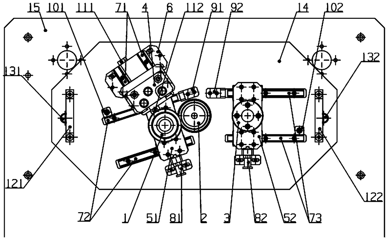
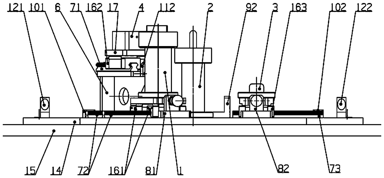
[0021] see figure 1 and figure 2 , the shaft assembly device of the front-wheel-drive automobile transmission assembly of the present invention includes an input shaft positioning part 1, an intermediate shaft positioning part 2, a differential positioning part 3, a shift fork shaft positioning part 4, a first support block 51, a second Two support blocks 52, left and right support frames 6, the first pair of guide rails 71, the second pair of guide rails 72, the third pair of guide rails 73, the first locking device 81, the second locking device 82, the first long limit block 91, The second long limiter 92, the first short limiter 101, the second short limiter 102, the first stopper 111, the second stopper 112, the bottom plate 14, the mounting plate 15, the first pair of sliders 161, The second pair of sliders 162 , the third pai...


PUM


Abstract

The invention provides an assembling device for a front-drive automobile transmission assembly shafting. The assembling device is good in assembling quality. A bottom plate is detachably installed on an installation plate. A first pair of guide rails, a second pair of guide rails and a third pair of guide rails are detachably installed on the bottom plate. The lower ends of the two guide rails of the first pair of guide rails are close to the middle portion of the upper guide rail of the second pair of guide rails and are inclined leftwards relative to the second pair of guide rails. The second pair of guide rails are inclined rightwards relative to the lower edge of the bottom plate. The inner ends of the third pair of guide rails are spaced with the inner ends of the second pair of guide rails and are parallel to the lower edge of the bottom plate. A left supporting frame and a right supporting frame are detachably installed on the bottom plate and are located on the outer sides of the two guide rails of the first pair of guide rails. A first locking device is connected with the outer end of a first supporting block, a second locking device is connected with the outer end of a second supporting block, and the first locking device and the second locking device are detachably installed on the bottom plate. A first long limiting block, a second long limiting block, a first short limiting block and a second short limiting block are detachably installed on the bottom plate, the first long limiting block and the first short limiting block are arranged at the left end and the right end of the second pair of guide rails, and the second long limiting block and the second short limiting block are arranged at the left end and the right end of the third pair of guide rails.

Description

technical field [0001] The invention relates to an assembly device of an automobile transmission, in particular to an assembly device for a shaft assembly of a front-wheel-drive automobile transmission assembly. Background technique [0002] At present, domestic and foreign transmission manufacturers usually assemble the shaft system of the front front drive vehicle transmission assembly by assembling the input shaft assembly, the intermediate shaft assembly, the differential assembly, and the shift fork shaft assembly according to their respective assembly methods. Finally, manually assemble the input shaft assembly, the intermediate shaft assembly, and the shift fork shaft assembly together on the box body through tooling, and then install the differential assembly to the corresponding position on the box body. The disadvantages of this are that the operation process is cumbersome, the labor intensity is high, time-consuming and labor-intensive, and in the manual assembly ...

Claims


Application Information

Patent Timeline
Patent Type & Authority Patents(China)
IPC IPC(8): F16H57/023F16H57/02
CPCF16H57/02F16H57/023F16H2057/005F16H2057/0062
Inventor 王国龙赖天胜刘元杰秦凌雷建明郭护雄龚永红唐世贵肖红梅
Owner CHONGQING TSINGSHAN IND
Why Eureka
Try Eureka