
car seat back lock

A technology for car seats and lock shells, which is applied to vehicle seats, movable seats, and vehicle parts, etc., which can solve the problems of space occupation, large opening torque, and laborious unlocking by users, so as to save space and reduce opening Torque, easy to unlock the effect

Active Publication Date: 2018-06-01
ZHEJIANG HUAYUAN LOCK IND CO LTD
View PDF7 Cites 0 Cited by
  • Summary
  • Abstract
  • Description
  • Claims
  • Application Information

AI Technical Summary

Problems solved by technology

[0002] At present, the car seat backrest locks provided on the market generally include a lock case and a cover plate. The lock case is provided with a lock leaf and an opening rocker arm. One end of the lock leaf is rotatably connected to the lock case. Swing towards the locking direction, the lock leaf is provided with a pin shaft and a lock groove, one end of the opening rocker arm is rotatably connected to the lock housing, the other end of the opening rocker arm is movably connected with the pin shaft, and the third section of the opening rocker arm is connected with the cable , the above-mentioned car seat backrest lock opening structure is located on the side of the lock and installed outside the seat, which not only takes up space, but also requires a large opening torque when unlocking, which makes it more difficult for the user to unlock. In addition, the above-mentioned The car seat back lock only has a single opening and locking function, and there is no obvious warning function. The user can only judge the status of the car seat back lock by repeated confirmation. Once the car seat is down and not locked , it is easy to cause safety accidents

Method used


Image

  • car seat back lock
  • car seat back lock
  • car seat back lock

Examples


Embodiment Construction

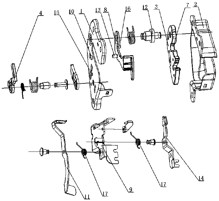
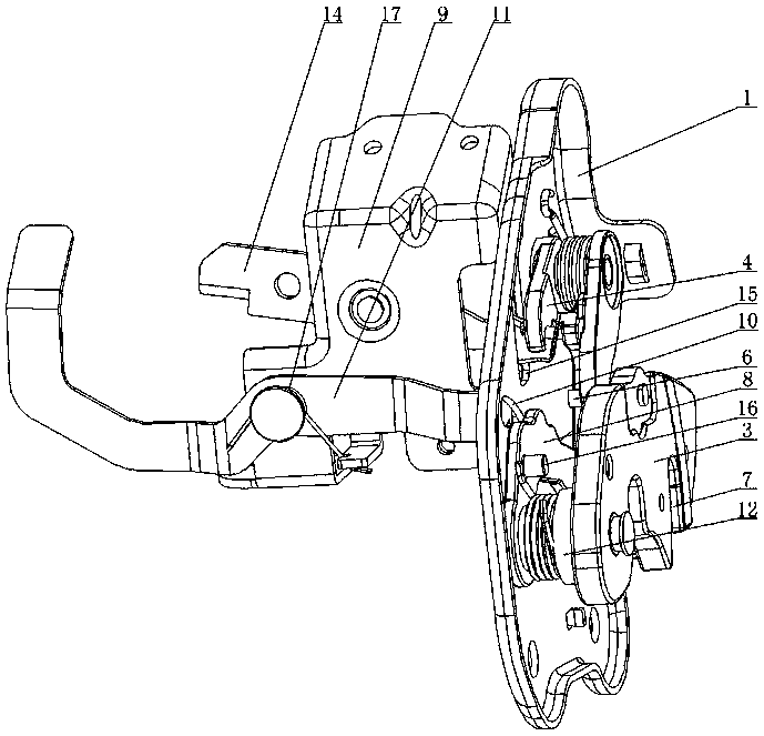
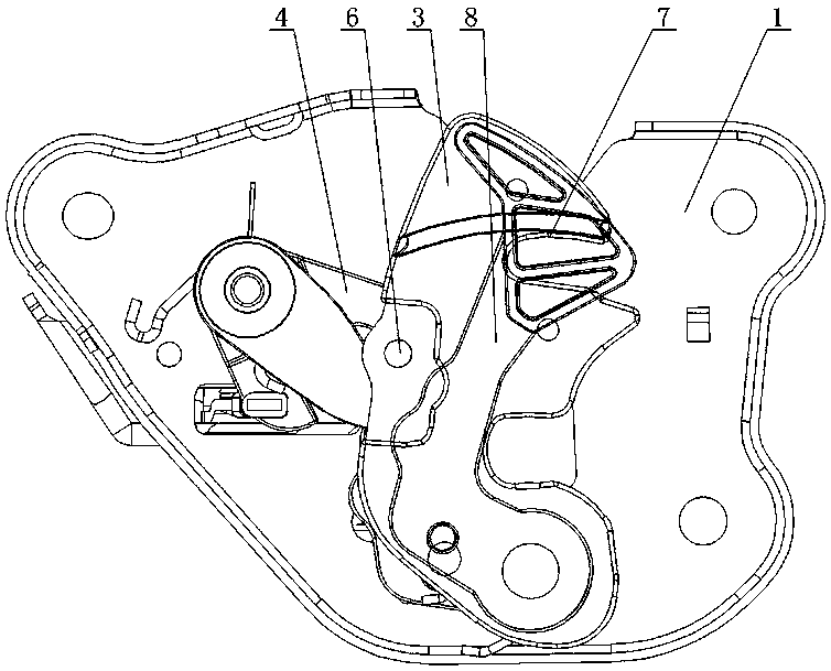
[0015] Such as figure 1 with figure 2 As shown, the car seat backrest lock provided by the present invention comprises a lock housing 1 and a cover plate 2, the lock housing 1 is provided with a lock leaf 3 and an opening rocker arm 4, one end of the lock leaf 3 is rotatably connected to the lock housing 1, and the lock The leaf 3 is equipped with a torsion spring to make it swing toward the locking direction, which is convenient for locking the lock bolt 5. The lock leaf 3 is provided with a pin shaft 6 and a lock groove 7. The lock groove 7 is convenient for the lock bolt 5 to snap in and open one end of the rocker arm 4. Rotationally connected to the lock case 1, the other end of the opening rocker arm 4 is movably connected with the pin shaft 6, the lock case 1 is provided with a mounting plate 9, and the lock case 1 is provided with a mounting plate 9, and the mounting plate 9 and the lock case 1 are in the shape of " L" type setting, the mounting plate 9 is rotatably c...


PUM


Abstract

The invention discloses an automobile seat back lock. The automobile seat back lock comprises a lock shell and a cover plate. A lock leaf and an unlocking rocker arm are arranged in the lock shell, one end of the lock leaf is rotationally connected to the lock shell, the lock leaf is provided with a torsional spring which promotes the lock leaf to swing towards the locking direction, the lock leaf is provided with a hinge pin and a lock groove, one end of the unlocking rocker arm is rotationally connected to the lock shell, and the other end of the unlocking rocker arm is movably connected with the hinge pin. An installation plate is arranged on the lock shell, the installation plate and the lock shell are arranged in an L shape, an unlocking lever is rotationally connected to the installation plate, a guide hole is formed in the lock shell, one end of the unlocking lever penetrates through the guide hole and is movably connected with the third end of the unlocking rocker arm, and the other end of the unlocking lever is connected with a pull rope. According to the automobile seat back lock, the unlocking structure is arranged on one face of the lock and can be installed in a seat, and therefore occupied space is saved; the lever principle is adopted for the unlocking lever, and therefore the unlocking force moment is greatly reduced; in addition, the lock has the early-warning function.

Description

technical field [0001] The invention relates to an automobile accessory, in particular to an automobile seat backrest lock. Background technique [0002] At present, the car seat backrest locks provided on the market generally include a lock case and a cover plate. The lock case is provided with a lock leaf and an opening rocker arm. One end of the lock leaf is rotatably connected to the lock case. Swing towards the locking direction, the lock leaf is provided with a pin shaft and a lock groove, one end of the opening rocker arm is rotatably connected to the lock housing, the other end of the opening rocker arm is movably connected with the pin shaft, and the third section of the opening rocker arm is connected with the cable , the above-mentioned car seat backrest lock opening structure is located on the side of the lock and installed outside the seat, which not only takes up space, but also requires a large opening torque when unlocking, which makes it more difficult for t...

Claims


Application Information

Patent Timeline
Patent Type & Authority Patents(China)
IPC IPC(8): B60N2/22
CPCB60N2/2245
Inventor 刘时权吴邦学
Owner ZHEJIANG HUAYUAN LOCK IND CO LTD
Learn More